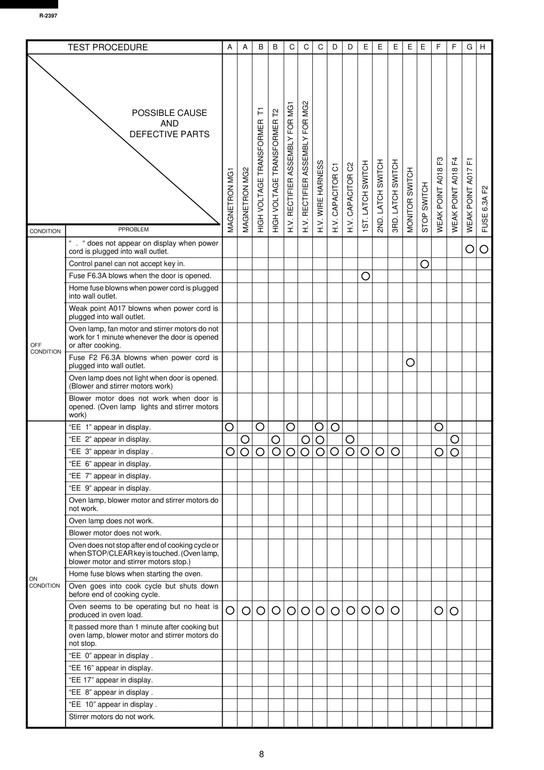
R-2397 specifications
The Sharp R-2397 is a high-performance microwave oven that combines advanced technology with user-friendly features, making it a popular choice for modern kitchens. This model stands out due to its sleek design and efficient functionality, catering to both cooking enthusiasts and busy households alike.One of the most notable features of the Sharp R-2397 is its powerful microwave cooking capabilities. With a wattage rating of 900 watts, it ensures that food is cooked evenly and quickly, allowing users to prepare meals in a fraction of the time compared to conventional ovens. The unit also offers multiple power levels, enabling precise cooking adjustments for various types of food, from defrosting to reheating and everything in between.
Another key characteristic of the R-2397 is its spacious interior. With a generous capacity of 23 liters, this microwave can accommodate larger dishes, making it suitable for families or individuals who enjoy hosting gatherings. The turntable feature promotes even cooking by rotating food continuously, ensuring that every inch is heated uniformly.
Additionally, the Sharp R-2397 is equipped with a range of convenient presets and auto-cook functions. These pre-programmed settings allow users to optimize cooking times for common dishes, such as popcorn, vegetables, and frozen meals, simplifying meal preparation and enhancing user experience. The intuitive control panel is designed to be user-friendly, ensuring that anyone can operate the microwave with ease.
Safety is also a significant consideration in the design of the Sharp R-2397. The unit comes with a child lock function, preventing accidental operation and ensuring that the oven is used safely in households with young children. This feature adds peace of mind for parents while using the appliance in their daily routines.
Moreover, the R-2397 incorporates a modern aesthetic that can fit into various kitchen styles. Its polished exterior and compact design make it both attractive and practical, with the added advantage of easy cleaning and maintenance.
In summary, the Sharp R-2397 is a versatile microwave oven that offers a blend of power, efficiency, and user-centric features. With its high wattage, spacious interior, smart presets, and safety measures, it is an excellent addition to any kitchen, catering to everyday cooking needs and helping to simplify meal times. Whether reheating leftovers or cooking a new recipe, the Sharp R-2397 sets itself apart as a reliable kitchen companion.

