R-2397


DESCRIPTION OF LSI


LSI(IZA646DR)


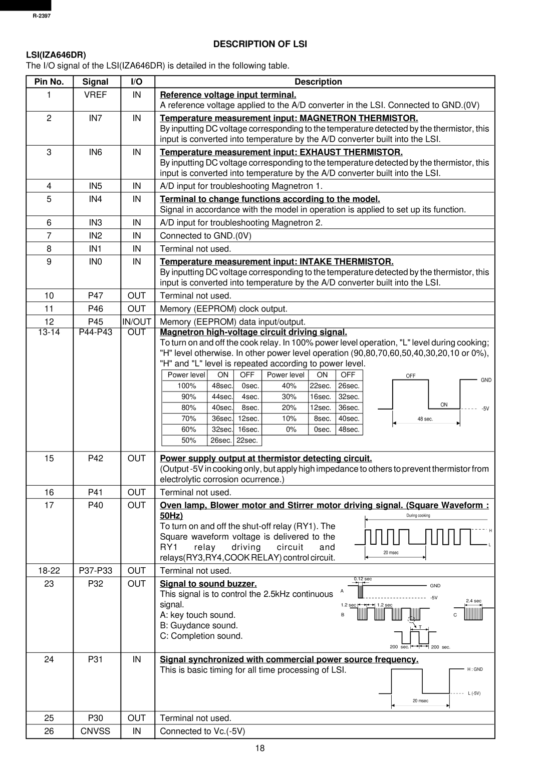
The I/O signal of the LSI(IZA646DR) is detailed in the following table.


Pin No.

Signal

I/O


Description


1

VREF

IN

Reference voltage input terminal.


A reference voltage applied to the A/D converter in the LSI. Connected to GND.(0V)

2

IN7

IN

Temperature measurement input: MAGNETRON THERMISTOR.


By inputting DC voltage corresponding to the temperature detected by the thermistor, this


input is converted into temperature by the A/D converter built into the LSI.

3

IN6

IN

Temperature measurement input: EXHAUST THERMISTOR.


By inputting DC voltage corresponding to the temperature detected by the thermistor, this


input is converted into temperature by the A/D converter built into the LSI.


4

IN5

IN

A/D input for troubleshooting Magnetron 1.


5

IN4

IN

Terminal to change functions according to the model.


Signal in accordance with the model in operation is applied to set up its function.


6

IN3

IN

A/D input for troubleshooting Magnetron 2.


7

IN2

IN

Connected to GND.(0V)


8

IN1

IN

Terminal not used.


9

IN0

IN

Temperature measurement input: INTAKE THERMISTOR.


By inputting DC voltage corresponding to the temperature detected by the thermistor, this


input is converted into temperature by the A/D converter built into the LSI.


10

P47

OUT

Terminal not used.


11

P46

OUT

Memory (EEPROM) clock output.


12

P45

IN/OUT

Memory (EEPROM) data input/output.


13-14

P44-P43

OUT

Magnetron high-voltage circuit driving signal.


To turn on and off the cook relay. In 100% power level operation, "L" level during cooking;


"H" level otherwise. In other power level operation (90,80,70,60,50,40,30,20,10 or 0%),


"H" and "L" level is repeated according to power level.


Power level

ON


OFF

Power level

ON

OFF


OFF


GND


100%

48sec.


0sec.

40%

22sec.

26sec.


90%

44sec.


4sec.

30%

16sec.

32sec.


ON


80%

40sec.


8sec.

20%

12sec.

36sec.


-5V


70%

36sec.

12sec.

10%

8sec.

40sec.


48 sec.


60%

32sec.

16sec.

0%

0sec.

48sec.


50%

26sec.

22sec.


15

P42

OUT

Power supply output at thermistor detecting circuit.


(Output -5V in cooking only, but apply high impedance to others to prevent thermistor from


electrolytic corrosion ocurrence.)


16

P41

OUT

Terminal not used.


17

P40

OUT

Oven lamp, Blower motor and Stirrer motor driving signal. (Square Waveform :


50Hz)


During cooking


To turn on and off the shut-off relay (RY1). The


H


Square waveform voltage is delivered to the


RY1

relay

driving

circuit

and


L


20 msec


relays(RY3,RY4,COOK RELAY) control circuit.


18-22

P37-P33

OUT

Terminal not used.


23

P32

OUT

Signal to sound buzzer.


0.12 sec


GND


This signal is to control the 2.5kHz continuous

A


-5V


signal.


1.2 sec


1.2 sec


2.4 sec


A: key touch sound.


B


C


B: Guydance sound.


T


C: Completion sound.


200sec.


200sec.


24

P31

IN

Signal synchronized with commercial power source frequency.


This is basic timing for all time processing of LSI.


H : GND


L (-5V)


20 msec


25

P30

OUT

Terminal not used.


26

CNVSS

IN

Connected to Vc.(-5V)


18

Page 20
Image 20
Sharp R-2397 service manual Description of LSI LSIIZA646DR

R-2397 specifications

The Sharp R-2397 is a high-performance microwave oven that combines advanced technology with user-friendly features, making it a popular choice for modern kitchens. This model stands out due to its sleek design and efficient functionality, catering to both cooking enthusiasts and busy households alike.

One of the most notable features of the Sharp R-2397 is its powerful microwave cooking capabilities. With a wattage rating of 900 watts, it ensures that food is cooked evenly and quickly, allowing users to prepare meals in a fraction of the time compared to conventional ovens. The unit also offers multiple power levels, enabling precise cooking adjustments for various types of food, from defrosting to reheating and everything in between.

Another key characteristic of the R-2397 is its spacious interior. With a generous capacity of 23 liters, this microwave can accommodate larger dishes, making it suitable for families or individuals who enjoy hosting gatherings. The turntable feature promotes even cooking by rotating food continuously, ensuring that every inch is heated uniformly.

Additionally, the Sharp R-2397 is equipped with a range of convenient presets and auto-cook functions. These pre-programmed settings allow users to optimize cooking times for common dishes, such as popcorn, vegetables, and frozen meals, simplifying meal preparation and enhancing user experience. The intuitive control panel is designed to be user-friendly, ensuring that anyone can operate the microwave with ease.

Safety is also a significant consideration in the design of the Sharp R-2397. The unit comes with a child lock function, preventing accidental operation and ensuring that the oven is used safely in households with young children. This feature adds peace of mind for parents while using the appliance in their daily routines.

Moreover, the R-2397 incorporates a modern aesthetic that can fit into various kitchen styles. Its polished exterior and compact design make it both attractive and practical, with the added advantage of easy cleaning and maintenance.

In summary, the Sharp R-2397 is a versatile microwave oven that offers a blend of power, efficiency, and user-centric features. With its high wattage, spacious interior, smart presets, and safety measures, it is an excellent addition to any kitchen, catering to everyday cooking needs and helping to simplify meal times. Whether reheating leftovers or cooking a new recipe, the Sharp R-2397 sets itself apart as a reliable kitchen companion.