XG-PH70X-N, XG-PH70X specifications
The Sharp XG-PH70X and XG-PH70X-N are high-performance projectors designed for professionals who require high-quality images and versatile connectivity options. These models offer a perfect blend of advanced technology and user-friendly features, making them ideal for a variety of applications, from corporate presentations to educational settings.One of the standout features of the XG-PH70X series is its impressive brightness level, peaking at 7,000 lumens. This high lumen output ensures clear and vivid images even in well-lit environments, which is crucial for maintaining visibility during presentations or lectures. The XG-PH70X utilizes Sharp’s proprietary DLP technology, which is renowned for delivering sharp, vibrant colors and high contrast ratios. This technology is particularly effective in producing images that are both detailed and lifelike.
In terms of resolution, the XG-PH70X supports native WUXGA (1920 x 1200), allowing it to display full HD content with impressive clarity. The projector also features a dynamic contrast ratio that enhances the depth and richness of the projected images, ensuring that both dark and bright scenes are rendered accurately.
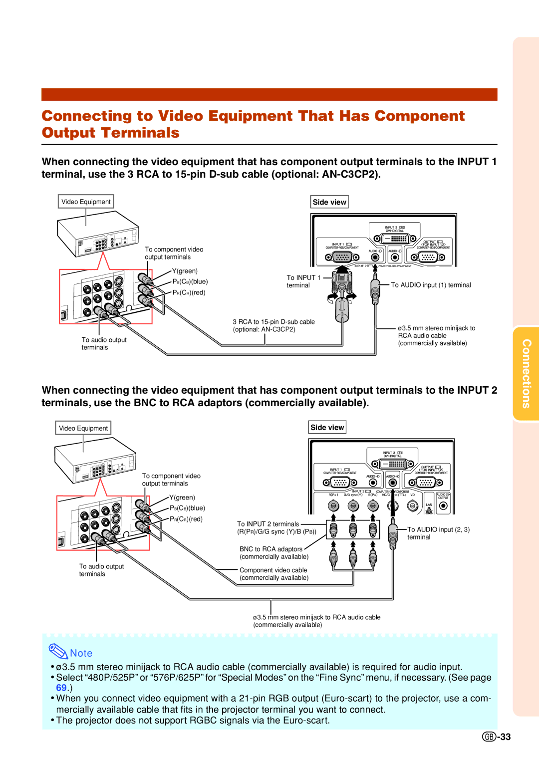
Connectivity options are another strong point of the XG-PH70X series. The projectors are equipped with multiple input ports, including HDMI, DisplayPort, and VGA, allowing for seamless integration with various devices such as laptops, Blu-ray players, and media servers. This versatility makes it easy to connect and display content from multiple sources.
Moreover, the XG-PH70X and XG-PH70X-N models come with advanced networking capabilities, including support for wired and wireless LAN connections. This feature allows users to share content from their devices effortlessly, contributing to a more collaborative and engaging presentation experience.
The projectors also offer an extended lamp life, which reduces maintenance costs and downtime. With options for eco-friendly modes, users can optimize the projector’s performance based on their specific needs, further enhancing its usability.
Portability is also a key feature, as these projectors are designed to be lightweight and easy to transport. This makes them suitable for traveling professionals who may need to set up presentations in various locations.
In summary, the Sharp XG-PH70X and XG-PH70X-N projectors are engineered to deliver exceptional performance, versatility, and ease of use. With their high brightness, advanced connectivity options, and user-friendly features, they are well-suited for demanding professional environments.

