R-525 specifications
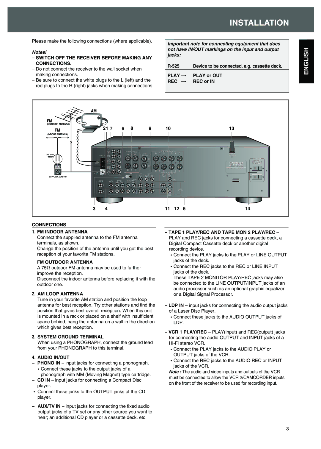
The Sherwood R-525 is a remarkable receiver that caters to audio enthusiasts seeking a robust and feature-rich home entertainment solution. Renowned for its quality performance and reliability, the R-525 stands out with its impressive array of specifications and technologies.One of the standout features of the Sherwood R-525 is its multi-channel audio capabilities. It supports a 5.1 channel surround sound configuration, allowing users to create an immersive listening experience that brings movies, music, and games to life. With a power output of around 100 watts per channel, the receiver ensures great clarity and dynamic range, making it suitable for a variety of acoustic environments.
In terms of connectivity, the R-525 offers multiple inputs and outputs, including HDMI, optical, and RCA connections. This versatility enables easy integration with a range of audio and visual devices like Blu-ray players, gaming consoles, and TVs. The inclusion of HDMI ARC support allows for simplified connectivity and the ability to control multiple devices with a single remote.
The Sherwood R-525 also excels in its built-in audio processing technologies. It is equipped with Dolby Digital and DTS decoding, ensuring that users can enjoy their favorite films and music with rich and detailed sound. The advanced DSP (Digital Signal Processing) technology further enhances the audio experience by optimizing sound quality based on the listener's environment.
Another key characteristic of the R-525 is its user-friendly interface. The receiver features an intuitive on-screen display, making it easy to navigate through settings and configurations. It also includes remote control functionality, allowing users to adjust settings without needing to be physically present at the unit.
For users who appreciate a tailored listening experience, the R-525 includes various sound modes and equalization options, allowing for customized sound profiles. These features ensure that listeners can adjust the audio output to suit their preferences or match the specific requirements of different content.
In terms of build quality, the Sherwood R-525 boasts a durable design, ensuring longevity and reliability. Its sleek and modern aesthetic integrates seamlessly into any home theater setup.
In summary, the Sherwood R-525 receiver delivers an impressive combination of power, connectivity, and advanced audio processing technologies. It serves as an excellent choice for those looking to enhance their home audio experience, making it a valuable addition to any entertainment system.

