Model 450 Series II User Guide
WIRING CONNECTIONS
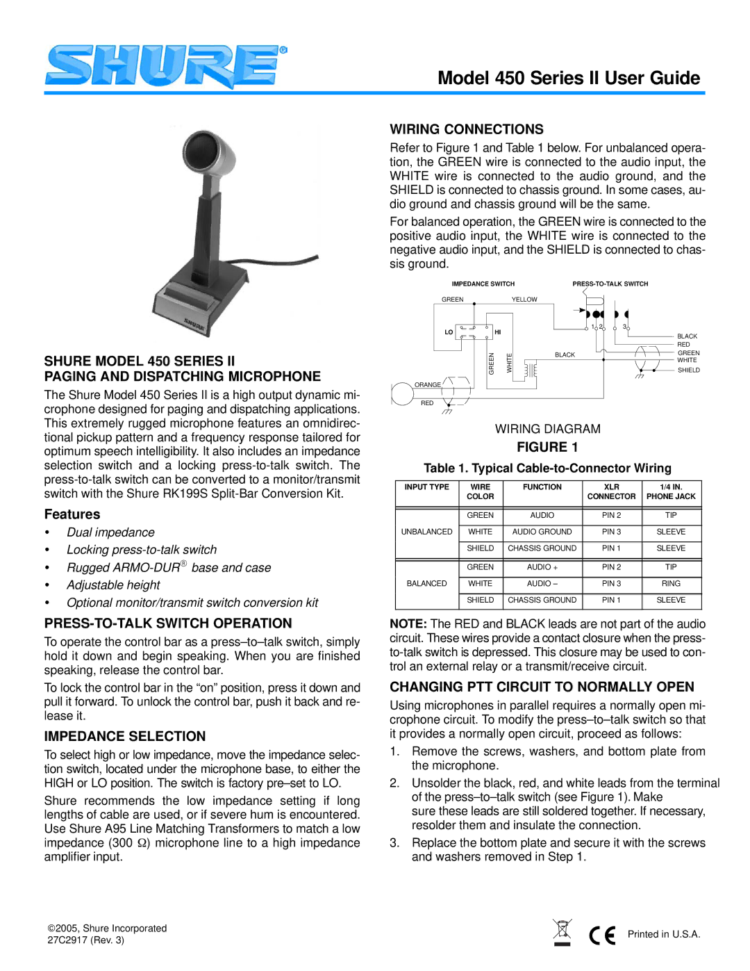
Refer to Figure 1 and Table 1 below. For unbalanced opera- tion, the GREEN wire is connected to the audio input, the WHITE wire is connected to the audio ground, and the SHIELD is connected to chassis ground. In some cases, au- dio ground and chassis ground will be the same.
For balanced operation, the GREEN wire is connected to the positive audio input, the WHITE wire is connected to the negative audio input, and the SHIELD is connected to chas- sis ground.
IMPEDANCE SWITCH |
SHURE MODEL 450 SERIES II
PAGING AND DISPATCHING MICROPHONE
GREEN
LO
ORANGE
YELLOW
| HI |
GREEN | WHITE |
1 | 2 | 3 |
BLACK
BLACK
RED
GREEN
WHITE
SHIELD
The Shure Model 450 Series II is a high output dynamic mi- crophone designed for paging and dispatching applications. This extremely rugged microphone features an omnidirec- tional pickup pattern and a frequency response tailored for optimum speech intelligibility. It also includes an impedance selection switch and a locking
Features
•Dual impedance
•Locking
•Rugged
•Adjustable height
•Optional monitor/transmit switch conversion kit
PRESS-TO-TALK SWITCH OPERATION
To operate the control bar as a
To lock the control bar in the “on” position, press it down and pull it forward. To unlock the control bar, push it back and re- lease it.
IMPEDANCE SELECTION
To select high or low impedance, move the impedance selec- tion switch, located under the microphone base, to either the HIGH or LO position. The switch is factory
Shure recommends the low impedance setting if long lengths of cable are used, or if severe hum is encountered. Use Shure A95 Line Matching Transformers to match a low impedance (300 Ω) microphone line to a high impedance amplifier input.
RED
WIRING DIAGRAM
FIGURE 1
Table 1. Typical Cable-to-Connector Wiring
INPUT TYPE | WIRE | FUNCTION | XLR | 1/4 IN. |
| COLOR |
| CONNECTOR | PHONE JACK |
|
|
|
|
|
|
|
|
|
|
| GREEN | AUDIO | PIN 2 | TIP |
|
|
|
|
|
UNBALANCED | WHITE | AUDIO GROUND | PIN 3 | SLEEVE |
|
|
|
|
|
| SHIELD | CHASSIS GROUND | PIN 1 | SLEEVE |
|
|
|
|
|
|
|
|
|
|
| GREEN | AUDIO + | PIN 2 | TIP |
|
|
|
|
|
BALANCED | WHITE | AUDIO – | PIN 3 | RING |
|
|
|
|
|
| SHIELD | CHASSIS GROUND | PIN 1 | SLEEVE |
|
|
|
|
|
NOTE: The RED and BLACK leads are not part of the audio circuit. These wires provide a contact closure when the press-
CHANGING PTT CIRCUIT TO NORMALLY OPEN
Using microphones in parallel requires a normally open mi- crophone circuit. To modify the
1.Remove the screws, washers, and bottom plate from the microphone.
2.Unsolder the black, red, and white leads from the terminal of the
sure these leads are still soldered together. If necessary, resolder them and insulate the connection.
3.Replace the bottom plate and secure it with the screws and washers removed in Step 1.
2005, Shure Incorporated |
| Printed in U.S.A. | ||
27C2917 (Rev. 3) |
|
|
| |
|
|
|
| |
|
|
| ||