duce approximately 28.3 volts at the DIRECT OUTPUT terminals (8,9), or 70 volts at the 70V OUTPUT terminals (11) when the
|
|
| ||
| LINE |
|
|
|
* |
|
| 3 - PIN MALE | |
| . |
| ATTENUAm | AUDIO CONNECTOR |
| r - - - i |
| ||
lr | I | I |
| |
|
| |||
| - I |
|
|
|
g | =8 |
|
|
|
I |
|
| - I |
|
5 | b |
|
| |
|
|
|
| |
u |
|
|
| INPUT |
FIGURE 10. 70-VOLT SYSTEM ATTENUATOR
BRIDGING CONNECTIONS
If greater power or optimum system reliability becomes extremely important, two Amplifiers may be connected in series (never in parallel!) to obtain an output of 400 watts into an
Connect the Amplifier balanced inputs out of phase as shown in Figure 11, Page 11, with the speaker load con- nected between the two 28V terminals of the DIRECT OUT- PUT Terminal Strips (9). Connect the two GND terminals together.
If a
ADDING HEADPHONE JACK TO SPEAKER CONNECTIONS
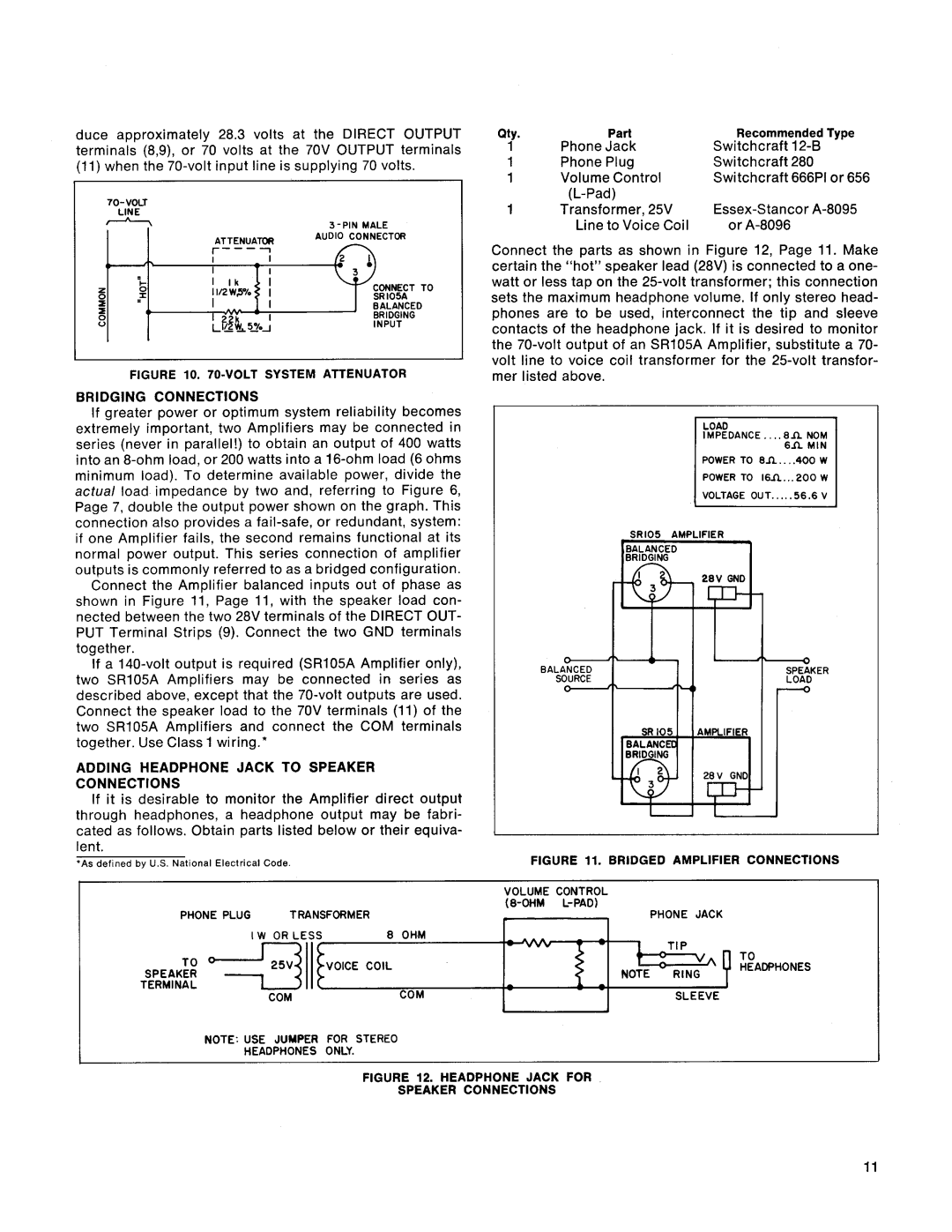
If it is desirable to monitor the Amplifier direct output through headphones, a headphone output may be fabri- cated as follows. Obtain parts listed below or their equiva- lent.
'As def~nedby U.S. Nat~onalElectrical Code
PHONE PLUG TRANSFORMER
| I W OR LESS | 8 OHM |
SPEAKER | COIL | |
| ||
TERMINALO | COM | |
| COM |
NOTE: USE JUMPER FOR STEREO
HEADPHONES ONLY.
Qty. | Part | Recommended Type |
1 | Phone Jack | Switchcraft |
1 | Phone Plug | Switchcraft 280 |
1 | Volume Control | Switchcraft 666Pl or 656 |
|
| |
1 | Transformer, 25V | |
| Line to Voice Coil | or |
Connect the parts as shown in Figure 12, Page 11. Make certain the "hot" speaker lead (28V) is connected to a one- watt or less tap on the
IMPEDANCE.. ..8n NOM
6 f i M I N
POWER TO e n . . .. 4oo w
POWER TO 1 6 n . . . 2 0 0 W
VOLTAGE OUT.....5 6 . 6 V
SR105 AMPLIFIER
BA | ER |
FIGURE 11. BRIDGED AMPLIFIER CONNECTIONS
VOLUME CONTROL
- |
| PHONE JACK |
| ||
- |
| |
- | NOTE | - |
RING | ||
| SLEEVE | |
|
|