Fume Hood Controller Owner’s Manual

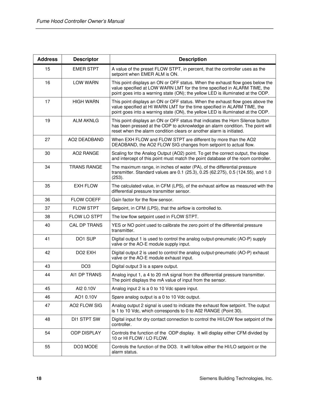
Address

Descriptor

Description


15

EMER STPT

A value of the preset FLOW STPT, in percent, that the controller uses as the


setpoint when EMER ALM is ON.


16

LOW WARN

This point displays an ON or OFF status. When the exhaust flow goes below the


value specified at LOW WARN LMT for the time specified in ALARM TIME, the


point goes into a warning state (ON); the yellow LED is illuminated at the ODP.


17

HIGH WARN

This point displays an ON or OFF status. When the exhaust flow goes above the


value specified at HI WARN LMT for the time specified in ALARM TIME, the


point goes into a warning state (ON), the yellow LED is illuminated at the ODP.

19

ALM AKNLG

This point displays an ON or OFF status that indicates the Horn Silence button


has been pressed at the ODP to acknowledge an alarm condition. The point will


reset when the alarm condition clears or another alarm is initiated.

27

AO2 DEADBAND

When EXH FLOW and FLOW STPT are different by more than the AO2


DEADBAND, the AO2 FLOW SIG changes from setpoint to actual flow.


30

AO2 RANGE

Scaling for the Analog Output (AO2) point. To get the correct output, the slope


and intercept of this point must match the point database of the room controller.


34

TRANS RANGE

The maximum range, in inches of water (PA), of the differential pressure


transmitter. Standard values are 0.1 (25.3), 0.25 (62.275), 0.5 (124.55), and 1.0


(253).

35

EXH FLOW

The calculated value, in CFM (LPS), of the exhaust airflow as measured with the


differential pressure transmitter sensor.


36

FLOW COEFF

Gain factor for the flow sensor.


37

FLOW STPT

Setpoint, in CFM (LPS), that the airflow is controlled to.


38

FLOW LO STPT

The low flow setpoint used in FLOW STPT.


40

CAL DP TRANS

YES or NO point used to calibrate the zero point of the differential pressure


transmitter.

41

DO1 SUP

Digital output 1 is used to control the analog output-pneumatic (AO-P) supply


valve or the AO-E module supply input.


42

DO2 EXH

Digital output 2 is used to control the analog output-pneumatic (AO-P) exhaust


valve or the AO-E module exhaust input.


43

DO3

Digital output 3 is a spare output.


44

AI1 DP TRANS

Analog input 1, a 4 to 20 mA signal from the differential pressure transmitter.


The point displays the mA value of input from the sensor.


45

AI2 0.10V

Analog input 2 is a 0 to 10 Vdc spare input.


46

AO1 0.10V

Spare analog output is a 0 to 10 Vdc output.


47

AO2 FLOW SIG

Analog output 2 signal is used to indicate the exhaust flow setpoint. The output


is 1 to 10 Vdc, which corresponds to 0 to A02 RANGE (Point 30).


48

DI1 STPT SW

Digital input for dry contact connection to control the HI/LOW flow setpoint of the


controller.

54

ODP DISPLAY

Controls the function of the ODP display. It will display either CFM divided by


10 or HI FLOW / LO FLOW.


55

DO3 MODE

Controls the function of the DO3. It will follow either the HI/LO setpoint or the


alarm status.


18

Siemens Building Technologies, Inc.

Page 26
Image 26
Siemens 125-5033 owner manual Flow Coeff

125-5033 specifications

The Siemens 125-5033 is a highly regarded circuit breaker in the world of electrical engineering and power distribution. Known for its robust design and versatile applications, this device offers a host of features that make it suitable for both commercial and industrial use.

One of the main features of the Siemens 125-5033 is its compact size. This allows for easy integration into existing systems without occupying excessive space, making it an ideal choice for facilities with limited room for electrical infrastructure. Its ability to handle high current ratings, typically around 125 amps, ensures that it can support a variety of electrical loads, making it versatile across different applications.

The Siemens 125-5033 employs advanced technologies, such as thermal-magnetic trip mechanisms. This allows for reliable protection against overloads and short circuits. The thermal component of the trip mechanism is designed to react to sustained overcurrent conditions, while the magnetic component responds instantaneously to short circuits. This dual-functionality ensures that the circuit breaker can effectively protect both the conductors and the connected equipment.

In terms of safety, the Siemens 125-5033 comes with advanced arc suppression technologies that minimize the risk of arcing during the circuit interrupting process. This not only enhances the longevity of the breaker but also safeguards personnel working near electrical installations. Additionally, the device features a clear, accessible reset mechanism, making it user-friendly and easy to operate in case of an interruption.

Another notable characteristic of the Siemens 125-5033 is its built-in ground fault protection option. This capability provides an added layer of safety, ensuring that any ground faults are detected and addressed promptly. It is particularly useful in environments where moisture or dust can compromise electrical safety.

The Siemens 125-5033 also boasts compatibility with various monitoring and control systems, enabling seamless communication and integration into smart building management systems. This feature allows facility managers to monitor power usage, identify potential issues, and optimize energy consumption effectively.

Overall, the Siemens 125-5033 circuit breaker is a reliable, safe, and technically advanced choice for those looking to enhance their electrical systems. Its compact size, dual-trip mechanism, ground fault protection, and compatibility with modern technologies make it a valuable asset for any facility looking to improve its electrical safety and efficiency.