IMPORTANT INFORMATION
K |
Fig O |
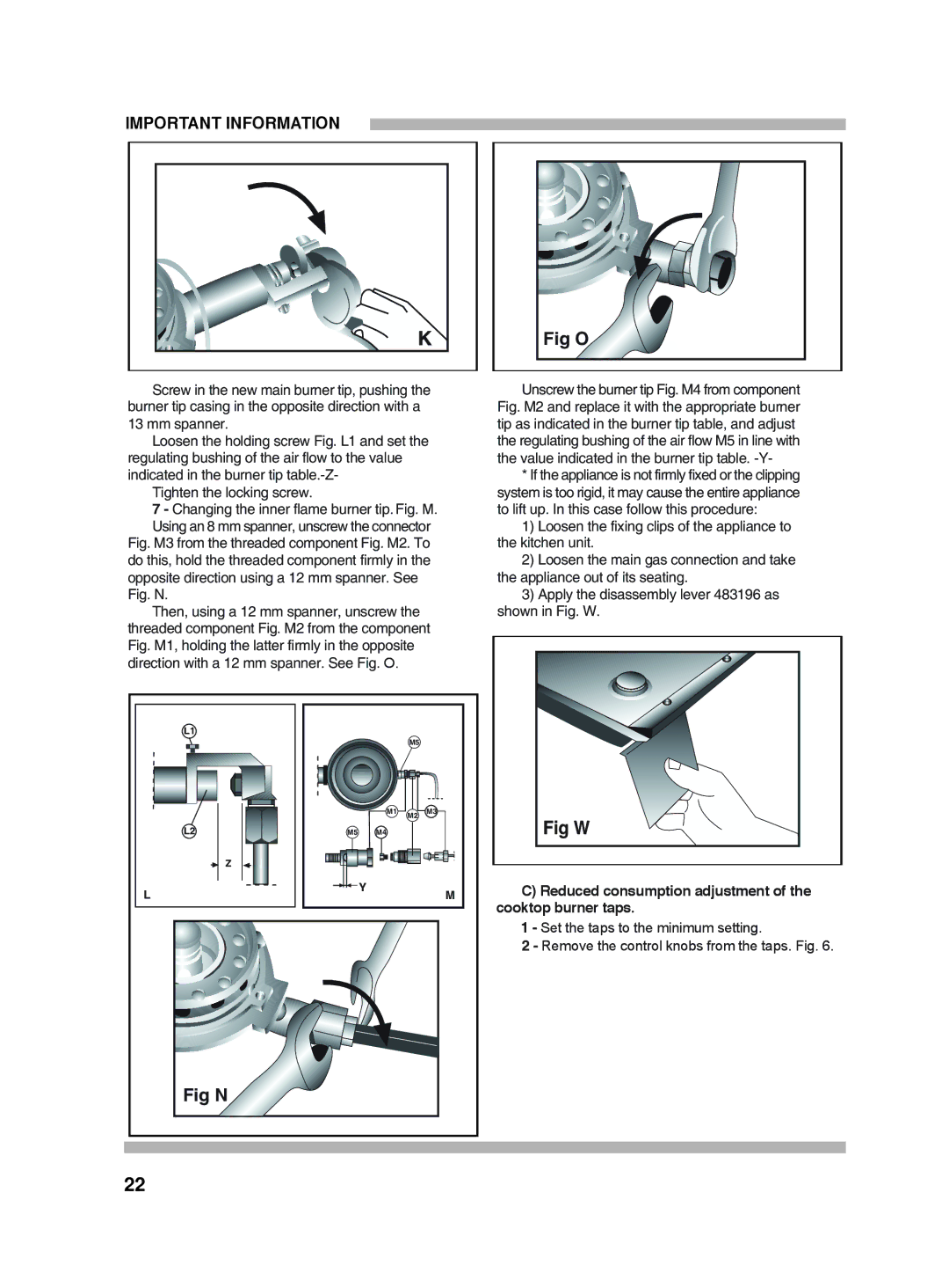
Screw in the new main burner tip, pushing the | Unscrew the burner tip Fig. M4 from component | ||||
burner tip casing in the opposite direction with a |
| Fig. M2 and replace it with the appropriate burner | |||
13 mm spanner. |
|
|
|
| tip as indicated in the burner tip table, and adjust |
Loosen the holding screw Fig. L1 and set the | the regulating bushing of the air flow M5 in line with | ||||
regulating bushing of the air flow to the value |
|
| the value indicated in the burner tip table. | ||
indicated in the burner tip |
|
|
|
| * If the appliance is not firmly fixed or the clipping |
Tighten the locking screw. |
|
|
|
| system is too rigid, it may cause the entire appliance |
7 - Changing the inner flame burner tip. Fig. M. | to lift up. In this case follow this procedure: | ||||
Using an 8 mm spanner, unscrew the connector | 1) Loosen the fixing clips of the appliance to | ||||
Fig. M3 from the threaded component Fig. M2. To | the kitchen unit. | ||||
do this, hold the threaded component firmly in the | 2) Loosen the main gas connection and take | ||||
opposite direction using a 12 mm spanner. See |
| the appliance out of its seating. | |||
Fig. N. |
|
|
|
| 3) Apply the disassembly lever 483196 as |
Then, using a 12 mm spanner, unscrew the |
| shown in Fig. W. | |||
threaded component Fig. M2 from the component |
| ||||
Fig. M1, holding the latter firmly in the opposite |
|
| |||
direction with a 12 mm spanner. See Fig. O. |
|
|
| ||
L1 |
|
|
|
|
|
|
|
| M5 |
|
|
|
| M1 | M2 | M3 | Fig W |
|
|
|
| ||
L2 | M5 | M4 |
|
| |
Z |
|
|
|
|
|
L |
| Y |
| M | C) Reduced consumption adjustment of the |
|
|
|
|
| cooktop burner taps. |
|
|
|
|
| 1 - Set the taps to the minimum setting. |
|
|
|
|
| 2 - Remove the control knobs from the taps. Fig. 6. |
Fig N |
|
|
|
|
|
22 |
|
|
|
|
|