Maintenance | 01.03 |
8.2Dimensioning of the burden resistors
Average DC current |
| A | 1300 | 1500 | 1950 |
| 2100 | 2660 | 2850 |
|
|
|
|
|
|
|
|
|
|
Burden voltage for 100% | V |
|
|
| 1 |
|
| ||
|
|
|
|
|
|
|
|
| |
| R75, R76 | Ω | 39 | 33 | 27 |
| 27 | 18 | 18 |
|
|
|
|
|
|
|
|
|
|
Burden resistors *) | R77, R78 | Ω | 39 | 33 | 27 |
| 33 | 22 | 18 |
|
|
|
|
|
|
|
|
|
|
| R79, R80 | Ω | 390 | 680 | 150 |
| 51 | 110 | 150 |
|
|
|
|
|
|
|
|
|
|
*) on module
Notes
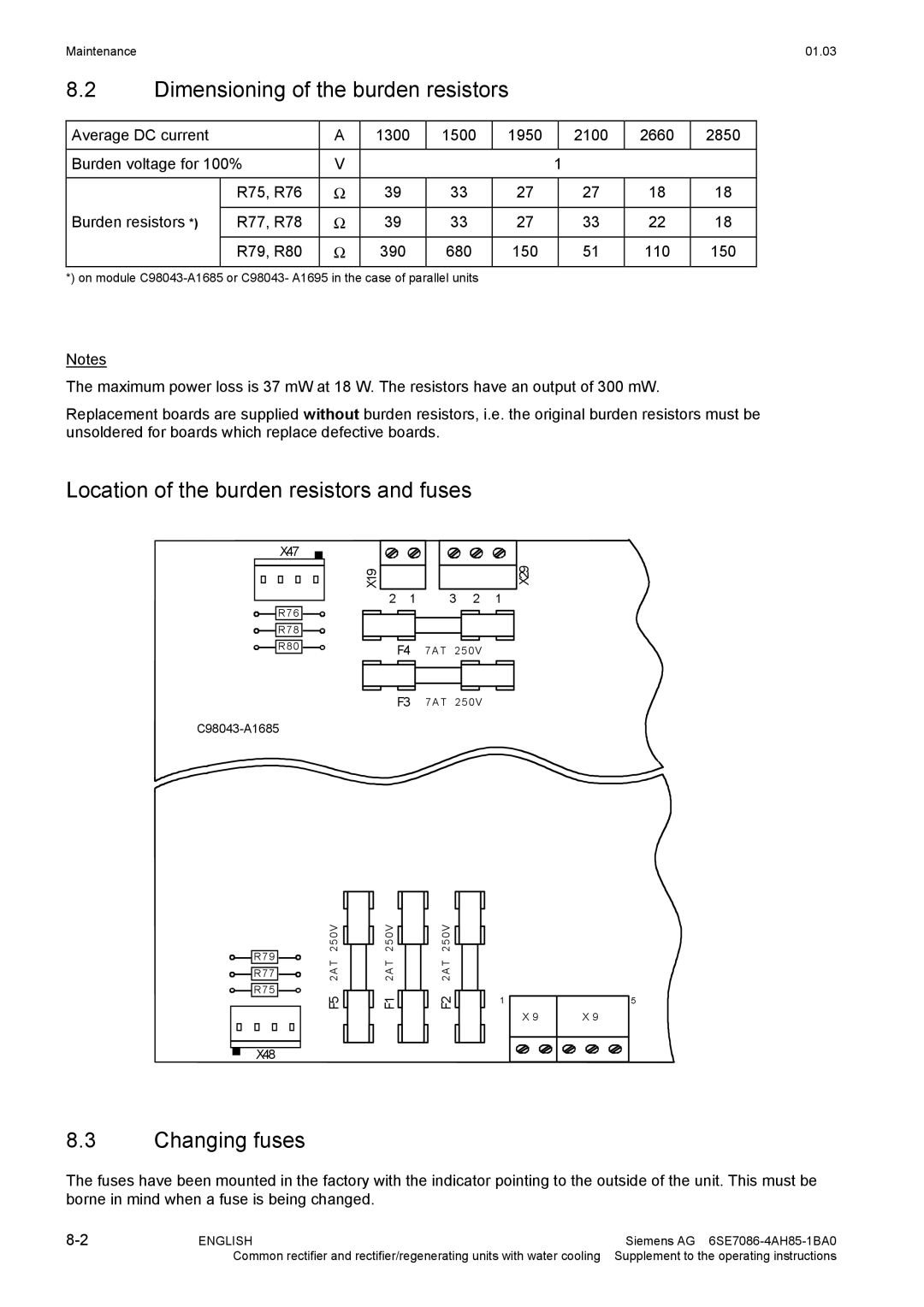
The maximum power loss is 37 mW at 18 W. The resistors have an output of 300 mW.
Replacement boards are supplied without burden resistors, i.e. the original burden resistors must be unsoldered for boards which replace defective boards.
Location of the burden resistors and fuses
|
|
|
|
| X47 |
|
|
|
|
|
|
|
|
|
|
|
|
|
| X29 | |||||||
|
|
|
|
|
|
|
|
|
|
|
|
|
|
|
|
|
| ||||||||||
|
|
|
|
|
|
|
|
|
|
|
|
|
|
|
|
|
|
|
|
|
|
|
|
|
|
| |
|
|
|
|
|
|
|
|
|
|
|
|
|
| X19 |
|
|
|
|
|
|
|
|
|
| |||
|
|
|
|
|
|
|
|
|
|
|
|
|
|
|
|
|
|
|
|
|
|
|
| ||||
|
|
|
|
|
|
|
|
|
|
|
|
|
|
|
|
|
|
|
|
|
|
|
| ||||
2 | 1 | 3 | 2 | 1 |
|
| |||||||||||||||||||||
|
|
|
| R 76 |
|
|
|
|
|
|
|
|
|
|
|
|
|
| |||||||||
|
|
|
|
|
|
|
|
|
|
|
|
|
| ||||||||||||||
|
|
|
|
|
|
|
|
|
|
|
|
|
|
|
|
|
|
| |||||||||
|
|
|
| R 78 |
|
|
|
|
|
|
|
|
|
|
|
|
|
|
|
| |||||||
|
|
|
|
|
|
|
|
|
|
|
|
|
|
|
|
|
|
| |||||||||
|
|
|
|
|
|
|
|
|
|
|
|
|
| ||||||||||||||
|
|
|
| R 80 |
|
|
|
|
|
|
|
|
|
|
| ||||||||||||
|
|
|
|
|
|
|
|
|
|
|
|
|
|
|
|
|
| ||||||||||
| F4 | 7A T 25 0V |
|
|
|
| |||||||||||||||||||||
|
|
|
|
|
|
|
|
|
|
|
| ||||||||||||||||
|
|
|
|
|
|
|
|
|
|
|
|
|
|
|
|
|
|
|
|
|
|
|
|
|
|
|
|
|
|
|
|
|
|
|
|
|
|
|
|
|
|
|
|
|
|
|
|
|
|
|
|
|
|
|
|
|
|
|
|
|
|
|
|
|
|
|
|
|
|
|
|
|
|
|
|
|
|
|
|
|
|
|
|
|
|
|
|
|
|
|
|
|
|
|
|
|
|
|
|
|
|
|
|
|
|
|
|
|
|
|
|
|
|
|
|
|
|
|
|
|
|
|
|
|
|
|
|
|
|
|
|
|
|
|
|
|
|
|
|
|
|
|
|
|
|
|
|
|
|
|
|
|
|
|
|
|
|
|
|
|
|
|
|
|
|
|
|
F3 7A T 25 0V
![]() R 79
R 79 ![]()
![]() R 77
R 77 ![]()
![]() R 75
R 75 ![]()
X48
25 0V |
|
|
|
|
| 25 0V |
|
|
|
|
| 25 0V |
|
|
|
|
|
|
|
|
|
| |||
|
|
|
|
|
|
| ||||||
|
|
|
|
|
|
|
|
|
| |||
2A T |
|
|
| 2A T |
|
|
| 2A T | ||||
F5 |
|
|
|
|
| F1 |
|
|
|
|
| F2 |
|
|
|
|
|
|
|
|
|
| |||
|
|
|
|
| ||||||||
1
X 9
5
X 9
8.3Changing fuses
The fuses have been mounted in the factory with the indicator pointing to the outside of the unit. This must be borne in mind when a fuse is being changed.
ENGLISH | Siemens AG | |
| Common rectifier and rectifier/regenerating units with water cooling | Supplement to the operating instructions |
