Assembly | 01.03 | |||||||||||||||||||||||||||||||||||||||
|
|
|
|
|
|
|
|
|
|
|
|
|
|
|
|
|
|
|
|
|
|
|
|
|
|
|
|
|
|
|
|
|
|
|
|
|
|
|
|
|
|
|
|
|
|
|
|
|
|
|
|
|
|
|
|
|
|
|
|
|
|
|
|
|
|
|
|
|
|
|
|
|
|
|
|
|
|
|
|
|
|
Unit
Wall penetration
Outgoing pipe |
|
|
|
|
|
|
|
Incoming pipe |
|
|
|
|
|
| Flexible connection |
|
|
|
|
|
| ||
|
|
|
|
|
| ||
|
|
|
|
|
| ||
|
|
|
|
|
| ||
|
|
|
|
|
| ||
|
|
|
|
|
| ||
Amot valve |
|
| |||||
|
| ||||||
|
| ||||||
|
| ||||||
|
| ||||||
| |||||||
| |||||||
|
| hose >1,5m, | |||||
e.g. pipe |
|
|
|
|
|
| |
|
|
|
|
|
| ||
|
|
|
|
|
|
| |
|
|
|
|
|
| ||
Cabinet
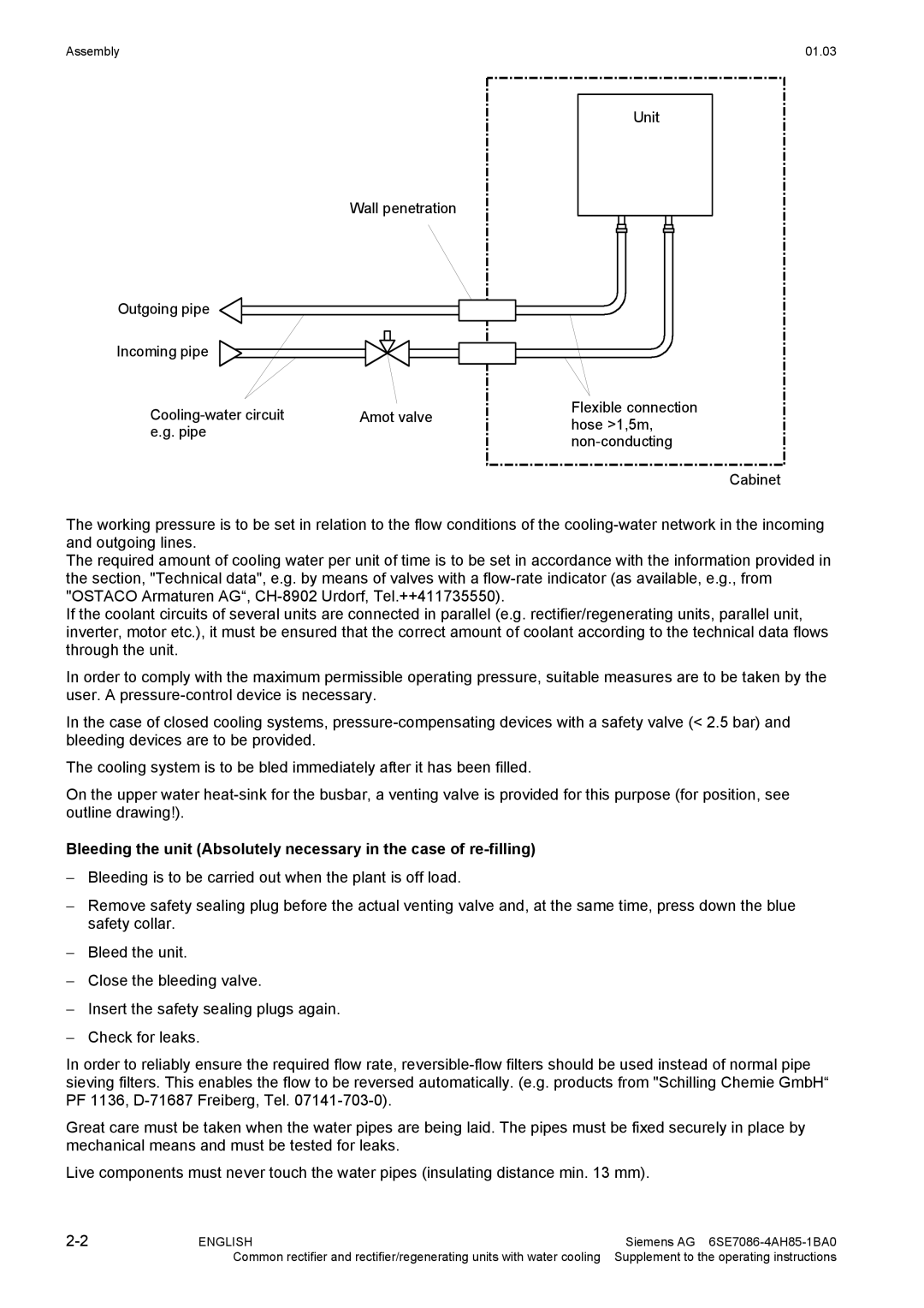
The working pressure is to be set in relation to the flow conditions of the
The required amount of cooling water per unit of time is to be set in accordance with the information provided in the section, "Technical data", e.g. by means of valves with a
If the coolant circuits of several units are connected in parallel (e.g. rectifier/regenerating units, parallel unit, inverter, motor etc.), it must be ensured that the correct amount of coolant according to the technical data flows through the unit.
In order to comply with the maximum permissible operating pressure, suitable measures are to be taken by the user. A
In the case of closed cooling systems,
The cooling system is to be bled immediately after it has been filled.
On the upper water
Bleeding the unit (Absolutely necessary in the case of
−Bleeding is to be carried out when the plant is off load.
−Remove safety sealing plug before the actual venting valve and, at the same time, press down the blue safety collar.
−Bleed the unit.
−Close the bleeding valve.
−Insert the safety sealing plugs again.
−Check for leaks.
In order to reliably ensure the required flow rate,
Great care must be taken when the water pipes are being laid. The pipes must be fixed securely in place by mechanical means and must be tested for leaks.
Live components must never touch the water pipes (insulating distance min. 13 mm).
ENGLISH | Siemens AG | |
| Common rectifier and rectifier/regenerating units with water cooling | Supplement to the operating instructions |
