01.03 | Connection |
3.2Power connections
|
| for M12 |
| ||
|
| (DC output) |
|
| (DC output) |
Common rectifier |
| C/L+ | Regenerating unit | C/L+ | |
|
|
|
| ||
|
| D/L- |
|
| D/L- |
|
| PE1 |
|
| PE2 |
U1/L1 | V1/L2 | W1/L3 | 1U2/1T1 | 1V2/1T2 | 1W2/1T3 |
|
| for M12 |
|
|
|
| Mains |
| |||
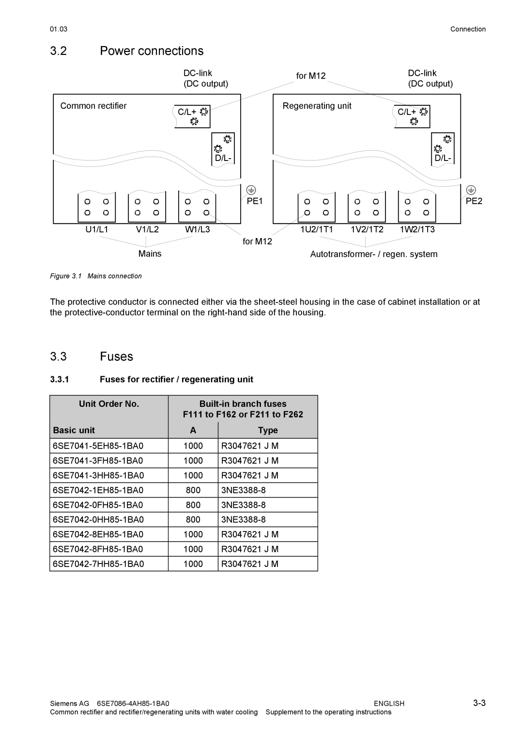
Figure 3.1 Mains connection
The protective conductor is connected either via the
3.3Fuses
3.3.1Fuses for rectifier / regenerating unit
| Unit Order No. |
|
|
| ||||
|
|
|
| F111 to F162 or F211 to F262 |
| |||
| Basic unit |
|
| A |
|
| Type |
|
|
| 1000 |
|
| R3047621 J M |
| ||
|
| 1000 |
|
| R3047621 J M |
| ||
|
|
|
|
|
|
|
| |
|
| 1000 |
|
| R3047621 J M |
| ||
|
| 800 |
|
|
| |||
|
| 800 |
|
|
| |||
|
|
|
|
|
|
| ||
|
| 800 |
|
| ||||
|
| 1000 |
|
| R3047621 J M |
| ||
|
| 1000 |
|
| R3047621 J M |
| ||
|
|
|
|
|
|
|
| |
|
| 1000 |
|
| R3047621 J M |
| ||
|
|
|
|
|
|
|
|
|
Siemens AG | ENGLISH | |
Common rectifier and rectifier/regenerating units with water cooling | Supplement to the operating instructions |
|
