Industry Automation and Drive Technologies - SCE
THEORY
CONTINUOUS AND SEQUENTIAL CONTROLS
Within the scope of basic automation, different logic control systems are developed that implement a limited, clearly defined function. The functions continuously process input signals and generate corresponding output signals. By means of different control signals, the functions can also be activated and parameterized. To implement complex process sequences
Sequential controls make step by step,
STRUCTURE OF STEP SEQUENCES
A step sequence is the alternating sequence of steps and transitions. The individual steps activate certain actions. The transitions control the change from one step to the next.
The first step of a step sequence is referred to as the start step. It is the unique entry point in the sequence and is always executed. The last step in a step sequence is correspondingly referred to as the end step. It is the only step in the sequence that does not have a sequence transition. After the end step is processed, the step sequence is terminated, or processing starts anew. The latter case is also referred to as sequence loop.
Steps and transitions are connected to each other with oriented diagrams. It is possible to connect a step with several sequential transitions; the reverse is possible also. A transition is enabled if all series connected steps are active and the step enabling condition is met.
In this case, first the immediately preceding steps are deactivated and then the immediate subsequent steps are activated.
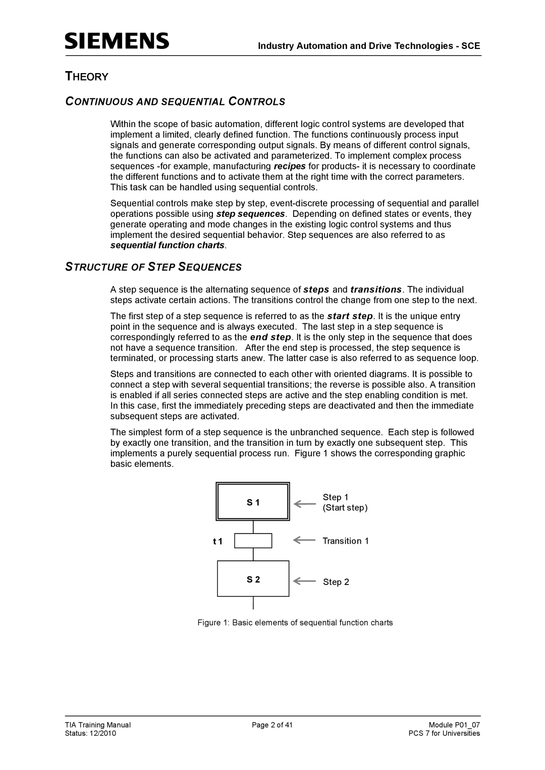
The simplest form of a step sequence is the unbranched sequence. Each step is followed by exactly one transition, and the transition in turn by exactly one subsequent step. This implements a purely sequential process run. Figure 1 shows the corresponding graphic basic elements.
S 1
Step 1 (Start step)
t 1 | Transition 1 |
S 2 | Step 2 |
Figure 1: Basic elements of sequential function charts
TIA Training Manual | Page 2 of 41 | Module P01_07 |
Status: 12/2010 |
| PCS 7 for Universities |
