2 Setting Up the Converter
2 Setting Up the Converter
2.1Overview
Before connecting the converter to your system, understand the connectors, LEDs and switches. This section describes each of the following features according to their functions:
•four
•one
•power module
•three configuration switches for communications
•manual and automatic operating modes
2.2RS-485 Communications Ports
The Isolated
|
|
|
|
|
| ||
RS485 | RS485 | RS485 | RS485 | ||||
+ | _ | + | _ | + | _ | + | _ |
|
|
|
| ||||
Figure 2.1 Connectors on Front Panel
Each port allows you to connect as many as 32 field devices on a single
For diagnostics, each port is equipped with a yellow transmit (Tx) LED and a green receive (Rx) LED, located on top of the device. The Tx LEDs blink during the transmission of data, which occurs on all ports simultaneously; only one Rx LED blinks when data is received. The LEDs are illustrated in Figure 2.2
Figure 2.2 Communications LEDs on the Top Panel
2.3RS-232 Communications Port
The converter is equipped with one
2.4Power Module
The interface of the converter’s power module is located on the rear panel, as illustrated in Figure 2.4. The power module includes an ON/OFF switch, an indicating power (PWR) LED, a 120 VAC power input, and a 15 VDC power output. The 15 VDC output is used to provide power to Static Trip IIITM trip units and SAMMSTM motor control and protection relays during testing. The filtered input next to the power switch is for providing line power to the converter. The power switch turns the converter on and off, and the PWR LED illuminates when the converter is turned on.
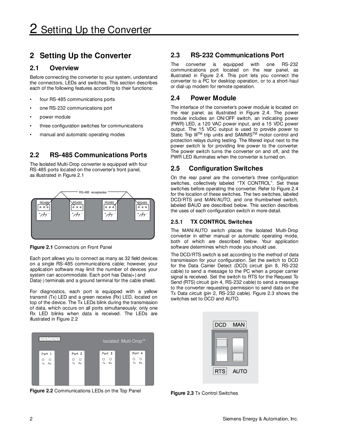
2.5Configuration Switches
On the rear panel are the converter’s three configuration switches, collectively labeled “TX CONTROL”. Set these switches before operating the converter. Refer to Figure 2.4 for the location of these switches. The two switches, labeled DCD/RTS and MAN/AUTO, and one thumbwheel switch, labeled BAUD are described below. This section describes the uses of each configuration switch in more detail.
2.5.1TX CONTROL Switches
The MAN/AUTO switch places the Isolated
The DCD/RTS switch is set according to the method of data transmission for your configuration. Set the switch to DCD for the Data Carrier Detect (DCD) circuit (pin 8,
Figure 2.3 Tx Control Switches
2 | Siemens Energy & Automation, Inc. |