Instruction Manual
6.0 INSTALLATION |
|
6.1 Gas Sensor Module Locations | 6.4 Power Supply |
The gas sensor module is a diffusion type sensor that should be located close to the anticipated source or destination of the gas hazard. For heavy gases such as H2S install the module within 24 inches of the ground. For lighter gases such as CO and com- bustible gases use a higher elevation.
After optimum locations are determined based on the above recommendations, consideration should be given to placing the sensors in locations that are accessible for calibration service. Slight adjustments to the location of the sensor may have little impact on effectivity but major effect on accessibility.
6.2 Mounting
To mount the monitor, remove the four svrews in the cover plate and move the cover plate aside. Use screws through the monitoring holes visible in the four corners of the housing to mount the monitor to a wall.
- The installation must meed any hazardous envi- ronmental codes for AC/DC electrical instrumenta- tion.
6.3 Wiring
Interconnect wiring from the controller to the module is by 4 conductor 22 AWG (or lower AWG) cable, conduit as necessary. Shielding is not required. For installations where the distance from the con- troller to the sensor is greater than 500 feet, 18 AWG cable is recommended.
The power supplied by the controlling device or an external power supply must meet the following speci- fications:
Voltage:9 - 24 VDC
Current: 250 mA
6.5 Alarm Devices
The internal relay is rated at 0.5 Amp, normally open dry contact rated at 100 VDC/130 VAC.
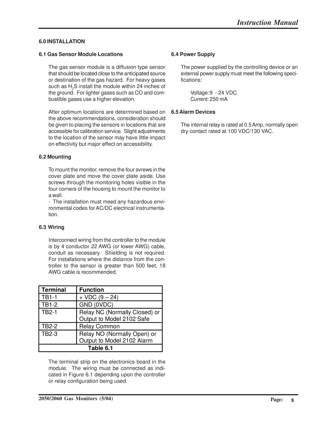
Terminal | Function |
+ VDC (9 – 24) | |
GND (0VDC) | |
Relay NC (Normally Closed) or | |
| Output to Model 2102 Safe |
Relay Common | |
Relay NO (Normally Open) or | |
| Output to Model 2102 Alarm |
| Table 6.1 |
The terminal strip on the electronics board in the module. The wiring must be connected as indi- cated in Figure 6.1 depending upon the controller or relay configuration being used.
2050/2060 Gas Monitors (5/04) | Page: | 8 |