Manuals
/
Sierra Wireless
/
TV and Video
/
CRT Television
Sierra Wireless
800TFT
specifications
Exploded View & Parts List
Models:
800TFT
1
47
54
54
Download
54 pages
60.48 Kb
44
45
46
47
48
49
50
51
Troubleshooting
Specifications
Parts list
Timing Chart
Disassembly and Reassembly
Adjustment Procedures
Alignments and Adjustments
Precautions
Using the OSD Service function
Video Switch
Page 47
Image 47
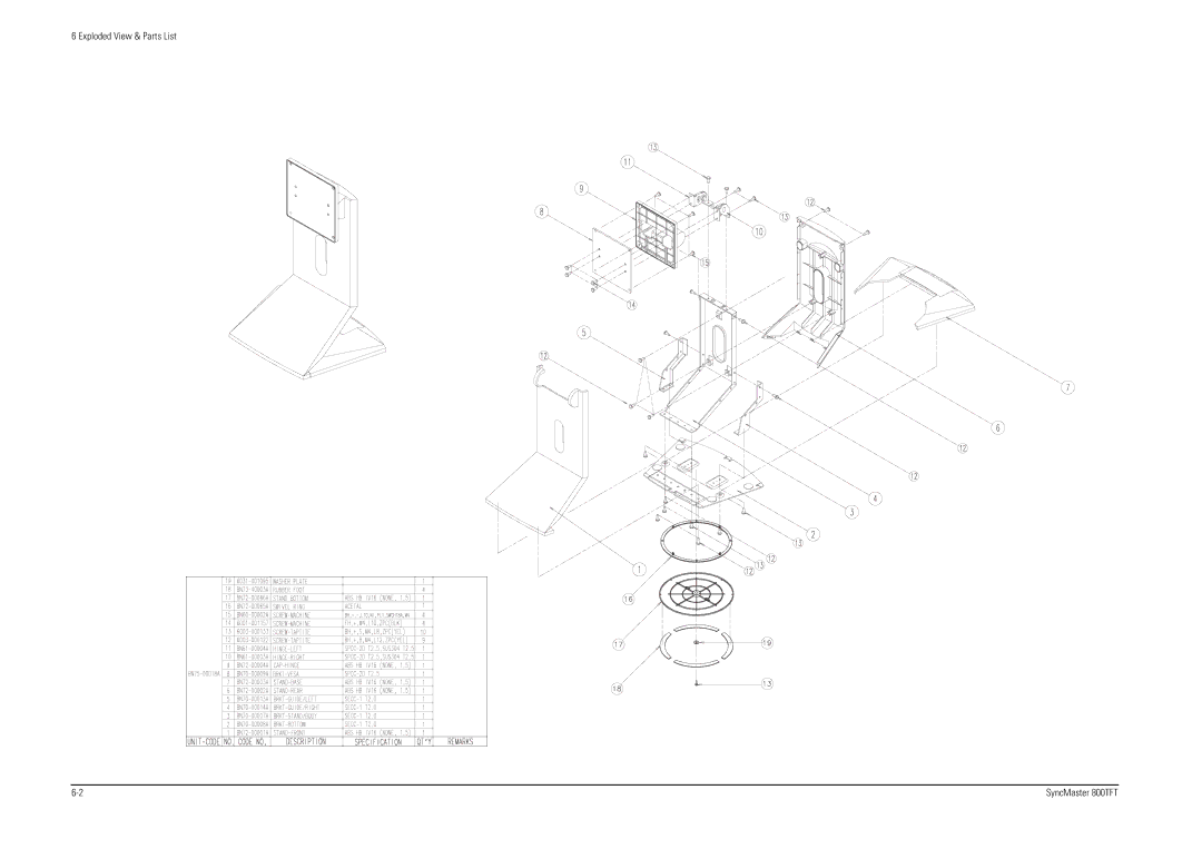
6 Exploded View & Parts List
6-2
SyncMaster 800TFT
Page 46
Page 48
Page 47
Image 47
Page 46
Page 48
Contents
Color Monitor
Safety Precautions
Precautions
Electrostatically Sensitive Devices ESD Precautions
Servicing Precautions
Specifications
Product Specifications
Type Pin No 13W3 Separate Composite
Pin Assignments
IBM Vesa
Timing Chart
Memo
Reassembly
Disassembly and Reassembly
Disassembly
Disassembly and Reassembly
Required Equipment
Alignments and Adjustments
Using the DDC Control JIG
Main Menu Sub Menu
Adjustment Procedures
Service Function Menu Screen
Using the OSD Service function
Alignments and Adjustments SyncMaster 800TFT
No Power
Troubleshooting
AD-SDA, AD-SCL
No Video
Waveforms
Waveforms
No OSD
Exploded View and Parts List
Exploded View & Parts List
Exploded View & Parts List SyncMaster 800TFT
Memo
Main PCB Parts
Electrical Parts List
Electrical Parts List
Remarks
C436
CIS
CN102
FILTER-EMI SMD
Chip
Electrical Parts List
R311
Electrical Parts List
Chip Network
RA412 RA413 RA414 RA415 RA416 RA417 RA418 X401 X501
Block Diagram
Video Switch
Block Diagrams
Wiring Diagram
Memo
Signal input Part Schematic Diagram
Schematic Diagrams
Scaler Chip Part Schematic Diagram
10-3
Micom Part Schematic Diagram
10-5 A/D converter Part Schematic Diagram
BN68-00049R-01
Exploded View and Parts List
Exploded View & Parts List
Exploded View & Parts List SyncMaster 800TFT
Memo
Schematic Diagrams
Scaler Chip Part Schematic Diagram
10-3
Micom Part Schematic Diagram
10-5 A/D converter Part Schematic Diagram
Top
Page
Image
Contents