Configuring the MP Modem to Report GPS and I/O
Data
A digital input can be connected to four of the pins on the DB15HD connector: Pins 3, 4, 11, and 12. (Pins 3 and 11 could alternatively be used for digital output.)
Note: Before using the input/output lines, you must configure them as inputs or outputs.
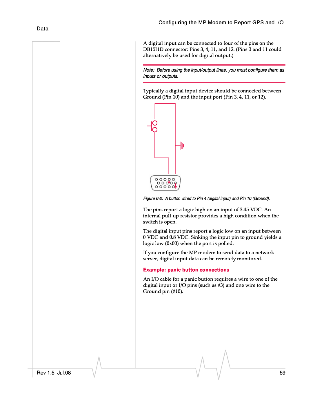
Typically a digital input device should be connected between
Ground (Pin 10) and the input port (Pin 3, 4, 11, or 12).
Figure
The pins report a logic high on an input of 3.45 VDC. An internal pull‐up resistor provides a high condition when the switch is open.
The digital input pins report a logic low on an input between 0 VDC and 0.8 VDC. Sinking the input pin to ground yields a logic low (0x00) when the port is polled.
If you configure the MP modem to send data to a network server, digital input data can be remotely monitored.
Example: panic button connections
An I/O cable for a panic button requires a wire to one of the digital input or I/O pins (such as #3) and one wire to the Ground pin (#10).
|
|
|
|
|
|
|
Rev 1.5 Jul.08 |
|
|
|
|
| 59 |
|
|
|