Overview
External Control Connector
Relates to the motion detection output signal.
Zoom and focus functions can be controlled using external siganals.
Power LED
Illuminates when power is supplied.
Video Output Jack
Used to connect an external video monitor in jack.
Communication Control Connector
Used to connect the Remote Controller (Optional). Includes external 'SYNC' signal input pin, which is used for the line lock function.
Includes the
Power Input Terminal
Power supply terminal (DC12V±10%).
Frame Ground Terminal
It is the GND terminal of the motion detection signal.
Connection
Connecting to Monitor
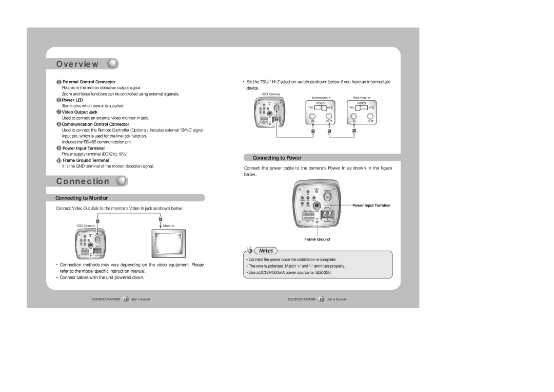
Connect Video Out Jack to the monitor's Video In jack as shown below.
CCD Camera | Monitor |
•Connection methods may vary depending on the video equipment. Please refer to the model specific instruction manual.
•Connect cables with the unit powered down.
COLOR CCD CAMERA 14 User’s Manual
• Set the 75Ω /
CCD Camera
Intermediate | End monitor |
Connecting to Power
Connect the power cable to the camera's Power In as shown in the figure below.
Power Input Terminal
Frame Ground
Notes
•Connect the power once the installation is complete.
•The wire is polarized. Match '+' and
•Use a DC12V/500mA power source for
COLOR CCD CAMERA 15 User’s Manual
