|
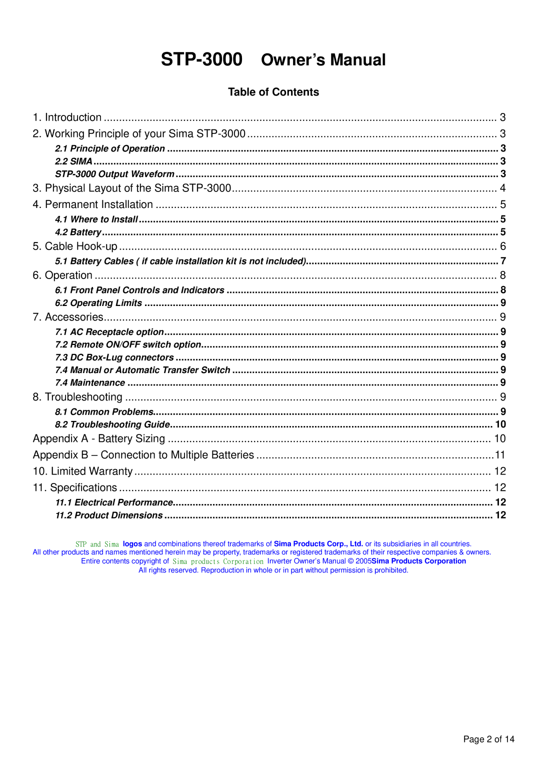
| Table of Contents |
|
1. | Introduction | 3 | |
2. Working Principle of your Sima | 3 | ||
| 2.1 | Principle of Operation | 3 |
| 2.2 | SIMA | 3 |
| 3 | ||
3. | Physical Layout of the Sima | 4 | |
4. | Permanent Installation | 5 | |
| 4.1 | Where to Install | 5 |
| 4.2 | Battery | 5 |
5. | Cable | 6 | |
| 5.1 | Battery Cables ( if cable installation kit is not included) | 7 |
6. | Operation | 8 | |
| 6.1 | Front Panel Controls and Indicators | 8 |
| 6.2 | Operating Limits | 9 |
7. | Accessories | 9 | |
| 7.1 | AC Receptacle option | 9 |
| 7.2 | Remote ON/OFF switch option | 9 |
| 7.3 DC | 9 | |
| 7.4 | Manual or Automatic Transfer Switch | 9 |
| 7.4 | Maintenance | 9 |
8. | Troubleshooting | 9 | |
| 8.1 Common Problems | 9 | |
| 8.2 | Troubleshooting Guide | 10 |
Appendix A - Battery Sizing | 10 | ||
Appendix B – Connection to Multiple Batteries | 11 | ||
10. Limited Warranty | 12 | ||
11. Specifications | 12 | ||
| 11.1 Electrical Performance | 12 | |
| 11.2 Product Dimensions | 12 | |
STP and Sima logos and combinations thereof trademarks of Sima Products Corp., Ltd. or its subsidiaries in all countries.
All other products and names mentioned herein may be property, trademarks or registered trademarks of their respective companies & owners. Entire contents copyright of Sima products Corporation Inverter Owner’s Manual © 2005Sima Products Corporation
All rights reserved. Reproduction in whole or in part without permission is prohibited.
Page 2 of 14
