,.
:..
.., :..
:Y:
The Landlord and Sovereign tractors have been designed for easy accessability to areas which need to be reached in making adjustments and performing maintenance. The un- derside of the frame has been left open to provide easy ac- cess to areas requiring lubrication, adjustment or repairs.
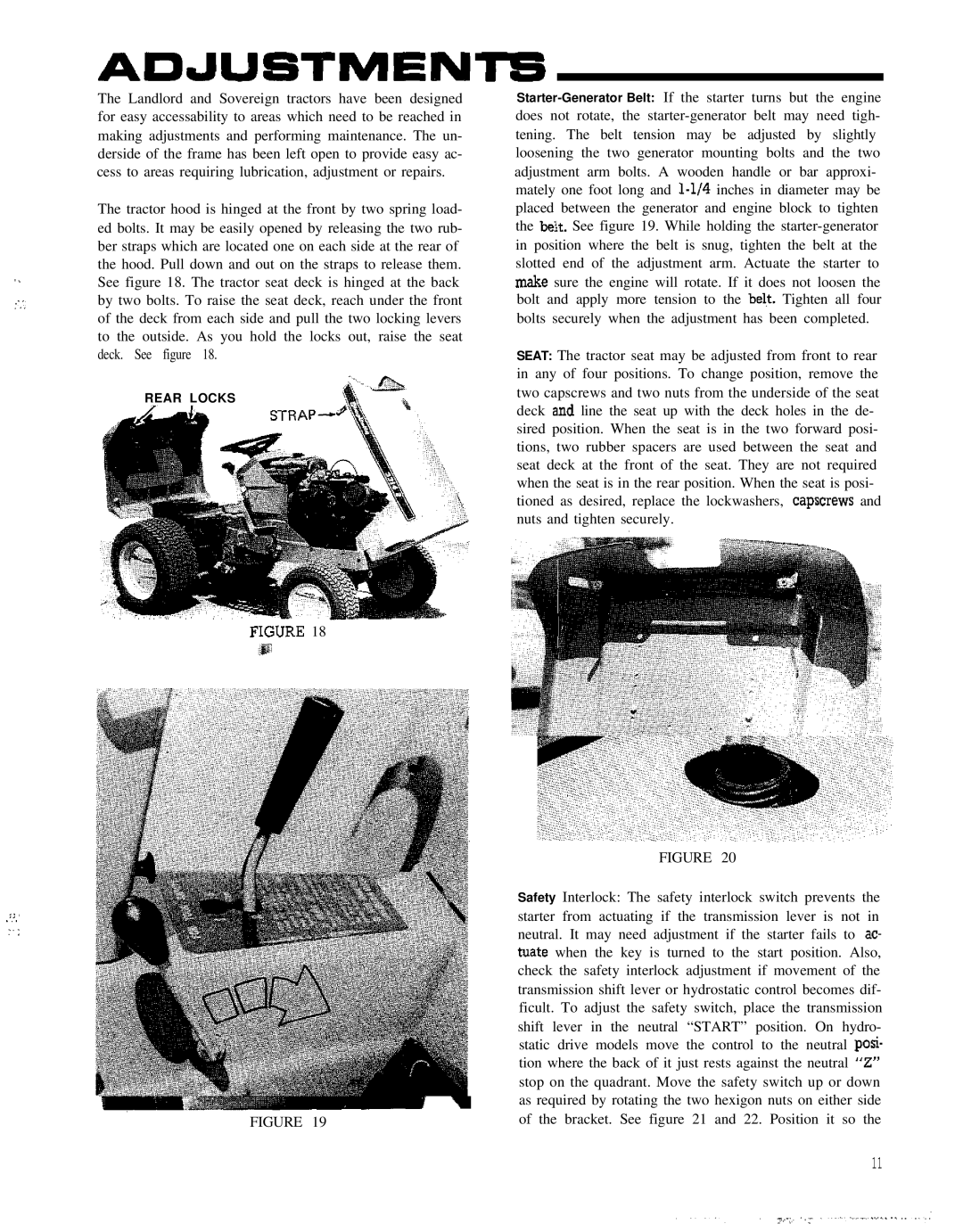
The tractor hood is hinged at the front by two spring load- ed bolts. It may be easily opened by releasing the two rub- ber straps which are located one on each side at the rear of the hood. Pull down and out on the straps to release them. See figure 18. The tractor seat deck is hinged at the back by two bolts. To raise the seat deck, reach under the front of the deck from each side and pull the two locking levers to the outside. As you hold the locks out, raise the seat deck. See figure 18.
REAR LOCKS
-
FIGURE 18
FIGURE 19
SEAT: The tractor seat may be adjusted from front to rear in any of four positions. To change position, remove the two capscrews and two nuts from the underside of the seat deck a,nd line the seat up with the deck holes in the de- sired position. When the seat is in the two forward posi- tions, two rubber spacers are used between the seat and seat deck at the front of the seat. They are not required when the seat is in the rear position. When the seat is posi- tioned as desired, replace the lockwashers, capscrews and nuts and tighten securely.
FIGURE 20
Safety Interlock: The safety interlock switch prevents the starter from actuating if the transmission lever is not in neutral. It may need adjustment if the starter fails to ac- tuate when the key is turned to the start position. Also, check the safety interlock adjustment if movement of the transmission shift lever or hydrostatic control becomes dif- ficult. To adjust the safety switch, place the transmission shift lever in the neutral “START” position. On hydro- static drive models move the control to the neutral posi- tion where the back of it just rests against the neutral “Z” stop on the quadrant. Move the safety switch up or down as required by rotating the two hexigon nuts on either side of the bracket. See figure 21 and 22. Position it so the
11