starter will actuate. If difficulty is experienced in moving the shift lever through the neutral position, raise the switch until the shift lever moves easily. Place a film of grease on the end of the safety interlock to reduce friction and wear.
VARIABLE SAFETY INTERLOCK
FIGURE 21
Power
The power
The belt guard located at the top of the power
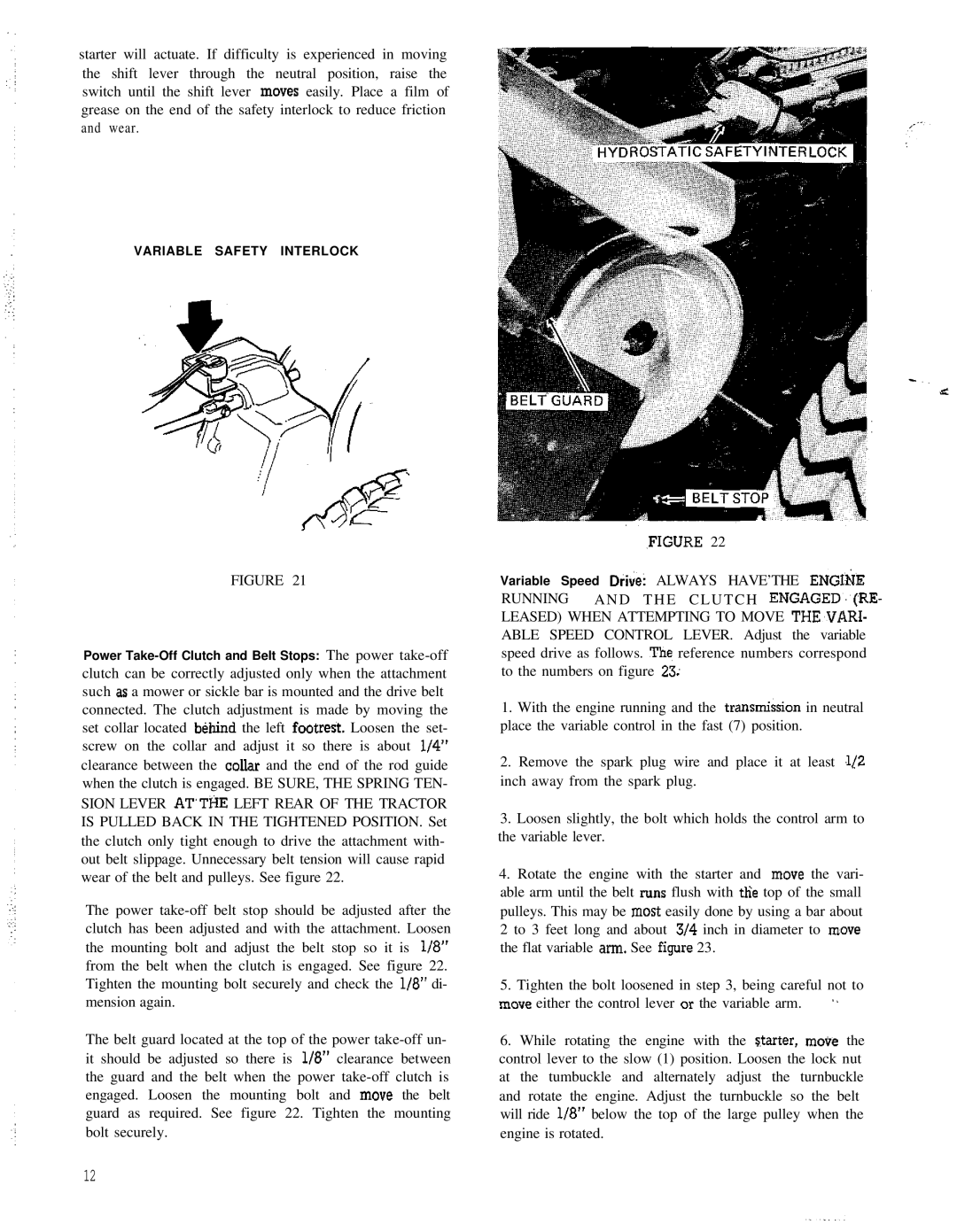
,FIGURE 22
Variable Speed D&e: ALWAYS HAVE’THE ENGI:&E
RUNNING A N D T H E C L U T C H ENGAGED.‘(RE- LEASED) WHEN ATTEMPTING TO MOVE THE,VARI- ABLE SPEED CONTROL LEVER. Adjust the variable speed drive as follows. The reference numbers correspond to the numbers on figure 23;
1.With the engine running and the transmi&ion in neutral place the variable control in the fast (7) position.
2.Remove the spark plug wire and place it at least .1/Z inch away from the spark plug.
3.Loosen slightly, the bolt which holds the control arm to the variable lever.
4.Rotate the engine with the starter and move the vari- able arm until the belt runs flush with tlie top of the small pulleys. This may be most easily done by using a bar about
2to 3 feet long and about 314 inch in diameter to move the flat variable arm. See figure 23.
5. Tighten the bolt loosened in step 3, being careful not to
move either the control lever or the variable arm. | ” |
6.While rotating the engine with the Starter, move the control lever to the slow (1) position. Loosen the lock nut at the tumbuckle and alternately adjust the turnbuckle and rotate the engine. Adjust the turnbuckle so the belt will ride l/8” below the top of the large pulley when the engine is rotated.
12