Troubleshooting, Adjustments, & Service
PARKING BRAKE ADJUSTMENT
Brake Adjustment
1.Disengage the PTO, stop the engine, block the front wheels, remove the ignition key, and lock the motion control levers into their neutral lock positions.
2.Elevate the rear end of the unit, making sure it is safely supported.
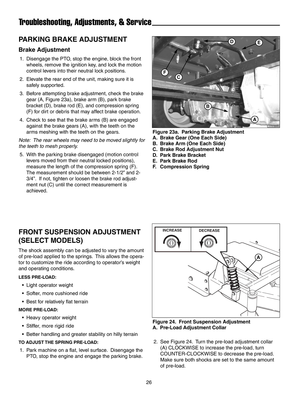
3.Before attempting brake adjustment, check the brake gear (A, Figure 23a), brake arm (B), park brake bracket (D), brake rod (E), and compression spring
(F) for dirt or debris that may affect brake operation.
4.Check to see that the brake arms (B) are engaged against the brake gears (A), with the teeth on the arms meshing with the teeth on the gears.
Note: The rear wheels may need to be moved slightly for the teeth to mesh properly.
5.With the parking brake disengaged (motion control levers moved from their neutral locked positions), measure the length of the compression spring (F). The measurement should be between
D E
F
C
B
A
Figure 23a. Parking Brake Adjustment
A.Brake Gear (One Each Side)
B.Brake Arm (One Each Side)
C.Brake Rod Adjustment Nut
D.Park Brake Bracket
E.Park Brake Rod
F.Compression Spring
FRONT SUSPENSION ADJUSTMENT (SELECT MODELS)
The shock assembly can be adjusted to vary the amount of
LESS
•Light operator weight
•Softer, more cushioned ride
•Best for relatively flat terrain
MORE
•Heavy operator weight
•Stiffer, more rigid ride
•Better handling and greater stability on hilly terrain
TO ADJUST THE SPRING
1.Park machine on a flat, level surface. Disengage the PTO, stop the engine and engage the parking brake.
INCREASE | DECREASE |
| A |
Figure 24. Front Suspension Adjustment
A.Pre-Load Adjustment Collar
2.See Figure 24. Turn the
(A) CLOCKWISE to increase the
26
