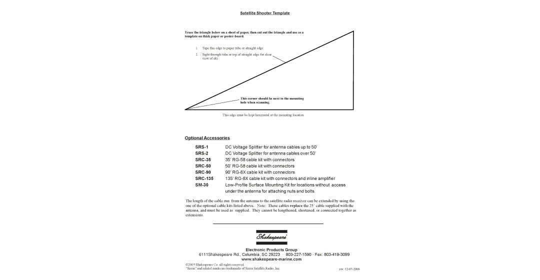
Satellite Shooter Template
Trace the triangle below on a sheet of paper, then cut out the triangle and use as a template on thick paper or
1.Tape this edge to paper tube or straight edge.
2.Sight through tube or top of straight edge for clear view of sky.
This corner should be next to the mounting hole when scanning.
This edge must be kept horizontal at the mounting location
Optional Accessories
| DC Voltage Splitter for antenna cables up to 50’ |
DC Voltage Splitter for antenna cables over 50’ | |
35’ | |
50’ | |
90’ | |
135’ | |
| |
| under the antenna for attaching nuts and bolts. |
The length of the cable run from the antenna to the satellite radio receiver can be extended by using the one of the optional cable kits listed above. Note: These cables replace the 25’ cable supplied with the antenna, and must be used as supplied. They cannot be lengthened, shortened, or connected together as extensions.
Electronic Products Group
6111Shakespeare Rd., Columbia, SC 29223 ·
©2005 Shakespeare Co. all rights reserved |
|
“Sirius” and related marks are trademarks of Sirius Satellite Radio, Inc. | rev. |