Assembly and adjustments |
|
| |
Fitting the tool rests | 1 |
|
|
The tool rests are required for each high speed |
|
| |
grinding wheel to assist in the grinding operation. |
|
|
|
To reduce the risk of injury, never |
|
|
|
! WARNING use a bench grinder on which the |
|
|
|
tool rest has not been fitted or where the tool rest | 3 |
|
|
has not been correctly adjusted. |
|
| |
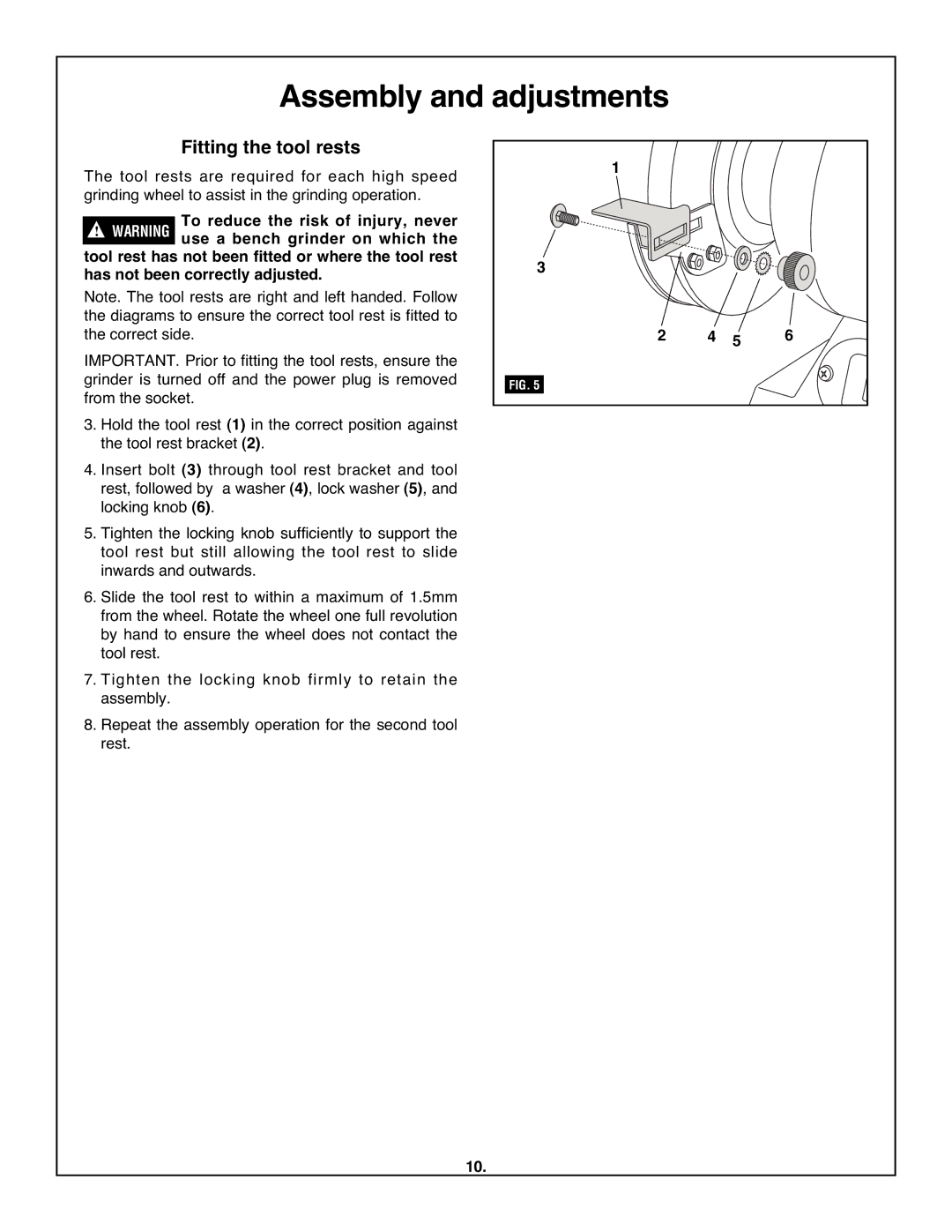
Note. The tool rests are right and left handed. Follow |
|
|
|
the diagrams to ensure the correct tool rest is fitted to | 2 |
| 6 |
the correct side. | 4 5 | ||
IMPORTANT. Prior to fitting the tool rests, ensure the | |||
grinder is turned off and the power plug is removed | FIG. 5 |
|
|
from the socket. |
|
|
|
3. Hold the tool rest (1) in the correct position against |
|
|
|
the tool rest bracket (2). |
|
|
|
4. Insert bolt (3) through tool rest bracket and tool |
|
|
|
rest, followed by a washer (4), lock washer (5), and |
|
|
|
locking knob (6). |
|
|
|
5. Tighten the locking knob sufficiently to support the |
|
|
|
tool rest but still allowing the tool rest to slide |
|
|
|
inwards and outwards. |
|
|
|
6. Slide the tool rest to within a maximum of 1.5mm |
|
|
|
from the wheel. Rotate the wheel one full revolution |
|
|
|
by hand to ensure the wheel does not contact the |
|
|
|
tool rest. |
|
|
|
7. Tighten the locking knob firmly to retain the |
|
|
|
assembly. |
|
|
|
8. Repeat the assembly operation for the second tool |
|
|
|
rest. |
|
|
|
10.
