SM 1619X03982
Operating Instructions
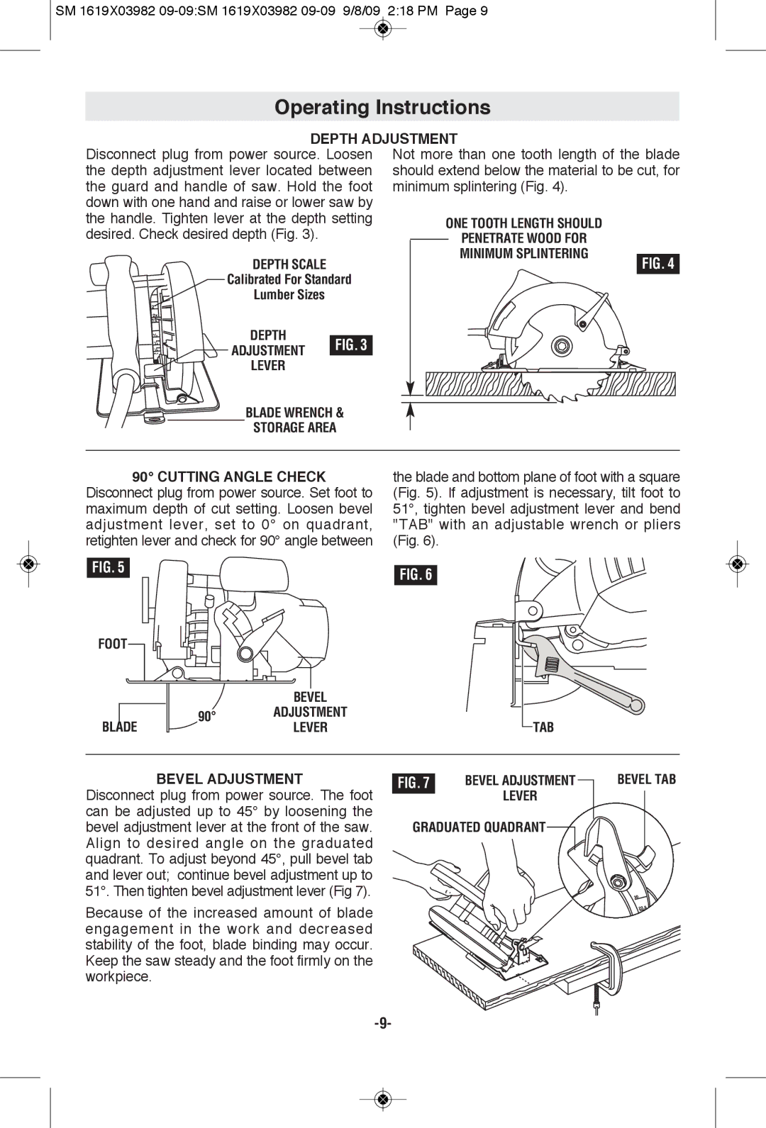
DEPTH ADjUSTMENT
Disconnect plug from power source. Loosen | Not more than one tooth length of the blade | ||
the depth adjustment lever located between | should extend below the material to be cut, for | ||
the guard and handle of saw. Hold the foot | minimum splintering (Fig. 4). | ||
down with one hand and raise or lower saw by |
|
|
|
the handle. Tighten lever at the depth setting |
|
|
|
desired. Check desired depth (Fig. 3). |
|
|
|
DEPTH SCALE
Calibrated For Standard
Lumber Sizes
DEPTH
ADJUSTMENT FIG. 3 LEVER
BLADE WRENCH &
STORAGE AREA
FIG. 4
90° CUTTING ANGLE CHECK
Disconnect plug from power source. Set foot to maximum depth of cut setting. Loosen bevel adjustment lever, set to 0° on quadrant, retighten lever and check for 90° angle between
the blade and bottom plane of foot with a square (Fig. 5). If adjustment is necessary, tilt foot to 51°, tighten bevel adjustment lever and bend "TAB" with an adjustable wrench or pliers (Fig. 6).
FIG. 5 |
| FIG. 6 | |
|
| ||
FOOT |
|
| |
|
| BEVEL | |
BLADE | 90° | ADJUSTMENT | |
LEVER | |||
|
 TAB
TAB
BEVEL ADjUSTMENT
Disconnect plug from power source. The foot can be adjusted up to 45° by loosening the bevel adjustment lever at the front of the saw. Align to desired angle on the graduated quadrant. To adjust beyond 45°, pull bevel tab and lever out; continue bevel adjustment up to 51°. Then tighten bevel adjustment lever (Fig 7).
Because of the increased amount of blade engagement in the work and decreased stability of the foot, blade binding may occur. Keep the saw steady and the foot firmly on the workpiece.
FIG. 7 | BEVEL ADJUSTMENT |
| LEVER |
|