Installation Instructions for
Model A50 Current Sensing Relay
CAUTION: For proper operation, the wire lead sponge bracket must carry a minimum of 4.0 amps.
If the current draw is less than 4.0 amps, wrap the lead wire around the bracket so that it passes
between the bracket and relay housing two or more times.
For Installation of a Humidifier with a Line Voltage Motor and a Low Voltage Control
CAUTION: DO NOT connect the 120V power to the furnace motor circuit. It can be powered off the hot 120V line before it enters the furnace.
1.To mount the unit, follow the
2.Follow these wiring instructions:
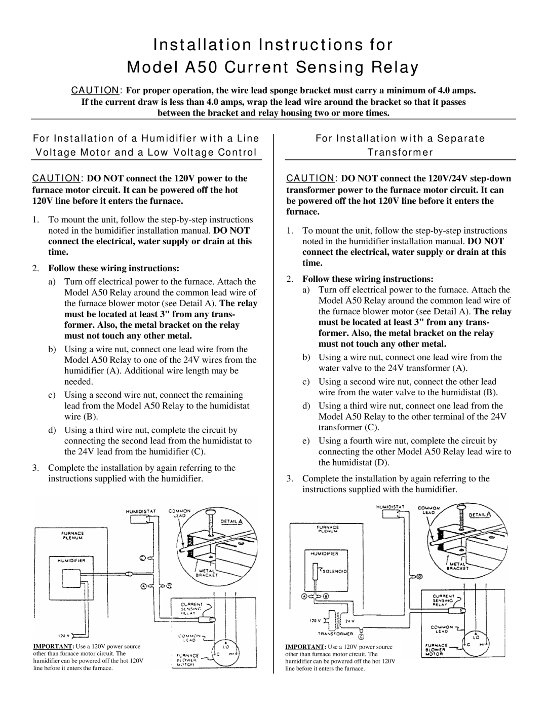
a)Turn off electrical power to the furnace. Attach the Model A50 Relay around the common lead wire of the furnace blower motor (see Detail A). The relay must be located at least 3" from any trans- former. Also, the metal bracket on the relay must not touch any other metal.
b)Using a wire nut, connect one lead wire from the Model A50 Relay to one of the 24V wires from the humidifier (A). Additional wire length may be needed.
c)Using a second wire nut, connect the remaining lead from the Model A50 Relay to the humidistat wire (B).
d)Using a third wire nut, complete the circuit by connecting the second lead from the humidistat to the 24V lead from the humidifier (C).
3.Complete the installation by again referring to the instructions supplied with the humidifier.
For Installation with a Separate
Transformer
CAUTION: DO NOT connect the 120V/24V
1.To mount the unit, follow the
2.Follow these wiring instructions:
a)Turn off electrical power to the furnace. Attach the Model A50 Relay around the common lead wire of the furnace blower motor (see Detail A). The relay must be located at least 3" from any trans- former. Also, the metal bracket on the relay must not touch any other metal.
b)Using a wire nut, connect one lead wire from the water valve to the 24V transformer (A).
c)Using a second wire nut, connect the other lead wire from the water valve to the humidistat (B).
d)Using a third wire nut, connect one lead from the Model A50 Relay to the other terminal of the 24V transformer (C).
e)Using a fourth wire nut, complete the circuit by connecting the other Model A50 Relay lead wire to the humidistat (D).
3.Complete the installation by again referring to the instructions supplied with the humidifier.
IMPORTANT: Use a 120V power source other than furnace motor circuit. The humidifier can be powered off the hot 120V line before it enters the furnace.
IMPORTANT: Use a 120V power source other than furnace motor circuit. The humidifier can be powered off the hot 120V line before it enters the furnace.