Optional Equipment Connections
Side Panel Connectors
ANT IN | AUDIO IN 1 | VIDEO |
| COMPONENT | AUDIO IN 2 |
| PC IN | HEADPHONE | AUDIO OUT | |||
R | L | Y | Pb | Pr R | L |
| R | L | ||||
|
|
|
|
| ||||||||
1 | 2 | 3 | 4 | 5 |
| 6 | 7 | 8 | 9 | 10 | 11 | 12 |
1.Antenna or cable In
2.Video /
3.Video /
4.Video In
5.
6.Component In
7.Component / PC Audio Right In
8.Component / PC Audio Left In
9.PC In
10.Headphone Jack
11.Audio Right Out 12.Audio Left Out
Rear Panel Connectors
DC 12V
1
1. DC 12V In
Procedure
Connect equipment as shown to Audio/Video input jacks.
Select the Video mode by pressing TV/AV button. Operate optional equipment as instructed in equipment manual.
Headphone jack: Plug an earphone or monaural headphones into this jack for private listening.
BASIC CONTROLS AND CONNECTIONS
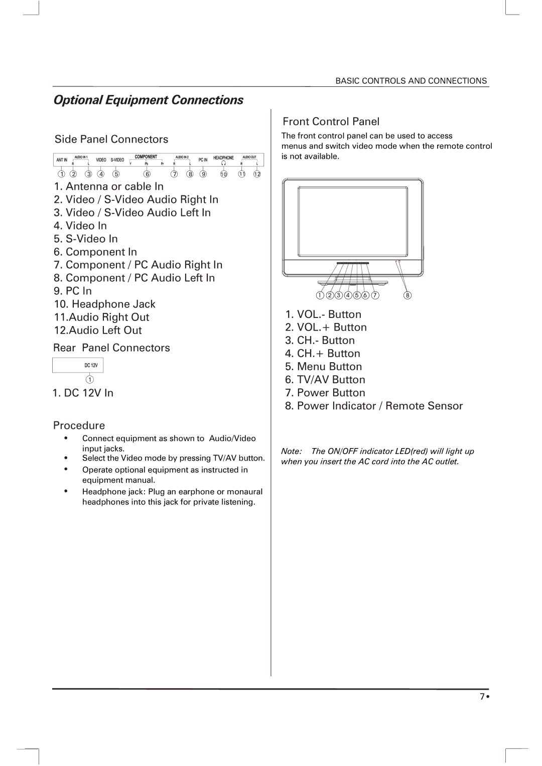
Front Control Panel
The front control panel can be used to access
menus and switch video mode when the remote control is not available.
1 | 2 | 3 | 4 | 5 | 6 | 7 | 8 |
1.VOL.- Button
2.VOL.+ Button
3.CH.- Button
4.CH.+ Button
5.Menu Button
6.TV/AV Button
7.Power Button
8.Power Indicator / Remote Sensor
Note: The ON/OFF indicator LED(red) will light up
when you insert the AC cord into the AC outlet.
7 ![]()