| 3 |
THE INSTALLATION INSTRUCTIONS IN THIS MANUAL ARE ABBREVIATED. SEE THE FRONT COVER OF THIS MANUAL FOR REFERENCES TO CODES AND STAN- DARDS.
BOILER LOCATION
Provide a level, solid foundation for the boiler. Location should be near the chimney so that the Flue Pipe Connector or Breeching to the chimney is short and direct.
A.The foundation must be capable of supporting the weight of the boiler when filled with water:
Boiler | Approximate Total Weight of Boiler |
Size | Assembly*, filled with water |
317 | |
405 | |
493 | |
581 | |
|
|
*Includes burner, circulator and controls
B.The
C.If boiler is to be located over buried conduit containing electric wires or telephone cables, consult local codes or the National Board of Fire Underwriters for specific require- ments.
MINIMUM CLEARANCE
Provide accessibility clearance of 24" from surfaces requiring servicing (top and front) and 18" on any side requiring pas- sage. The boiler shall be installed with the following MINIMUM clearances from combustible materials:
A.CHIMNEY CONNECTOR-18"
B.BACK AND SIDES- 6" EXCEPT as limited by 18" clear-
ance from chimney connector
NOTE: Except in closets and alcoves, clearances above in (A) and (B) may be reduced by providing forms of protection as specified in NFPA 31, latest edition.
CHIMNEY REQUIREMENTS (see NFPA 31, latest edition)
A.The chimney must be constructed in accordance with all local applicable codes and the National Board of Fire Underwriters. See boiler models and rating table shown on page 2 for chimney sizes.
B.Check chimney condition.
Existing chimneys and stacks may have deteriorated; with- out repairs their use would be hazardous. Before connect- ing to an old chimney or stack:
1.Clean it.
2.Inspect it thoroughly.
3.Remove obstructions.
4.Replace worn sections of metal stacks.
5.Seal bad masonry joints.
6.Repair damaged lining.
C.Where more than one appliance vents into a common chimney, the area of the common breeching should at least equal the area of the largest appliance flue plus 50% of the additional flue areas.
D.Breeching area must not be reduced at connection into chimney. Breeching must be inserted into, but not beyond, inside of chimney liner.
E.Chimney height shall extend at least 3 feet above where it passes through the roof of the building, and at least 2 feet above any ridge within 10 feet of the chimney.
F.The use of a vent cap, where permitted by code, gives additional protection against adverse wind conditions and precipitation.
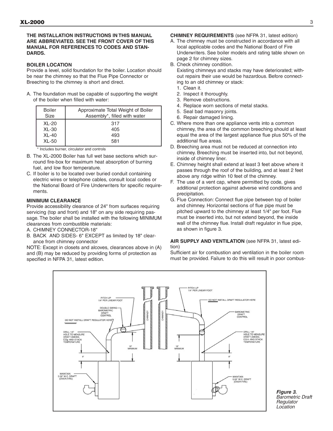
G.Flue Connection: Connect flue pipe between top of boiler and chimney. Horizontal sections of flue pipe must be pitched upward to the chimney at least 1/4" per foot. Flue must be inserted into, but not extend beyond, the inside wall of the chimney flue. Install draft regulator in flue pipe, as shown in figure 3.
AIR SUPPLY AND VENTILATION (see NFPA 31, latest edi- tion)
Sufficient air for combustion and ventilation in the boiler room must be provided. Failure to do this will result in poor combus-
Figure 3.
Barometric Draft
Regulator
Location