Chapter 2 Hardware Installation
2.1. Panel Layout
2.1.1. Front Panel
Figure 2-1 Front Panel
1 - 4 LAN port socket (RJ-45). These are where you will connect to devices on your local area network. (adapter, hub, or switch, e.g.)
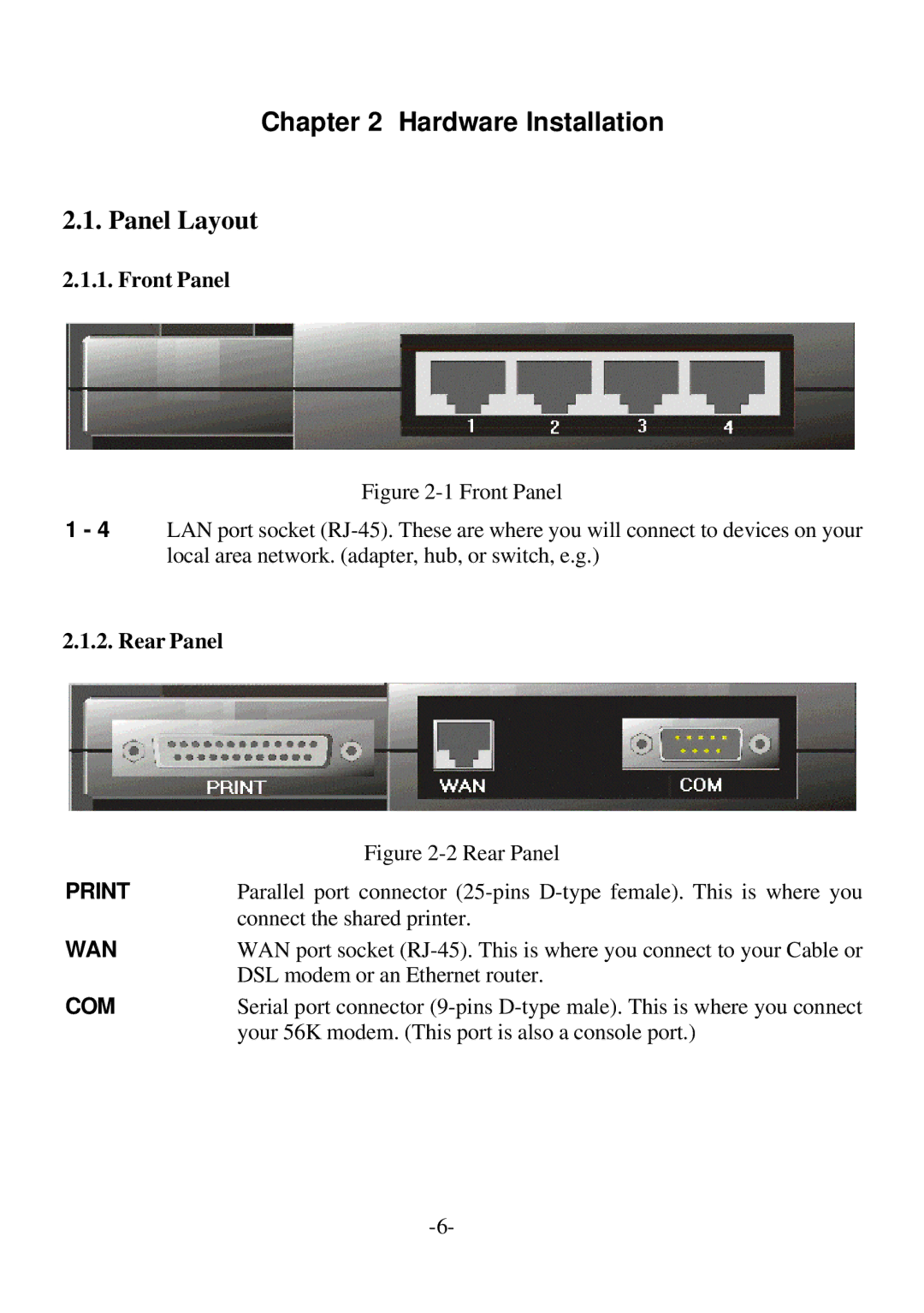
2.1.2. Rear Panel
| Figure |
Parallel port connector | |
| connect the shared printer. |
WAN | WAN port socket |
| DSL modem or an Ethernet router. |
COM | Serial port connector |
| your 56K modem. (This port is also a console port.) |