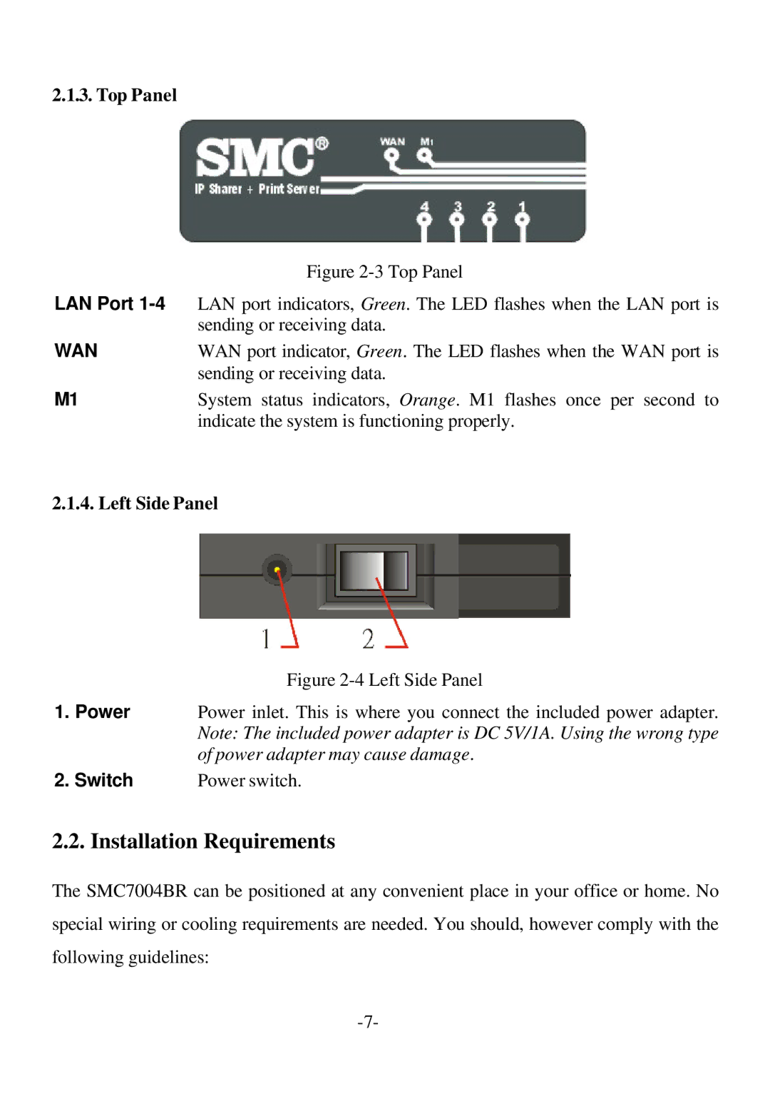
2.1.3. Top Panel
Figure 2-3 Top Panel
LAN Port 1-4 LAN port indicators, Green. The LED flashes when the LAN port is
| sending or receiving data. |
WAN | WAN port indicator, Green. The LED flashes when the WAN port is |
| sending or receiving data. |
M1 | System status indicators, Orange. M1 flashes once per second to |
| indicate the system is functioning properly. |
2.1.4. Left Side Panel
Figure 2-4 Left Side Panel
1.Power Power inlet. This is where you connect the included power adapter. Note: The included power adapter is DC 5V/1A. Using the wrong type of power adapter may cause damage.
2. Switch | Power switch. |
2.2. Installation Requirements
The SMC7004BR can be positioned at any convenient place in your office or home. No
special wiring or cooling requirements are needed. You should, however comply with the
following guidelines: