INSTALLING THE SWITCH
6.The Module LED on the switch’s front panel should turn green to confirm that the module is correctly installed and ready to use.
Installing an Optional
SFP or XFP Transceiver into the Switch
37 | 38 |
|
|
|
|
|
|
|
|
|
|
| |
| 39 | 40 |
|
|
|
|
|
|
|
|
|
| |
|
| 41 | 42 |
|
|
|
|
|
|
|
|
| |
|
|
| 43 | 44 |
|
|
|
|
|
|
|
| |
|
|
|
| 45 | 46 |
|
|
|
|
|
|
| |
|
|
|
|
| 47 | 48 |
|
|
|
|
|
|
| Stack | Master | |
|
| ||
|
|
| Pwr |
Master |
|
| RPS |
Select | Stack | ||
| Module | ||
|
| ID | |
|
|
| Diag |
|
|
| Stack |
|
|
| Link |
|
|
| Console |
| 45 |
|
|
|
|
| 46 |
|
|
| 47 |
TigerStack | |
10/100/1000M | |
8848 | II |
| 48 |
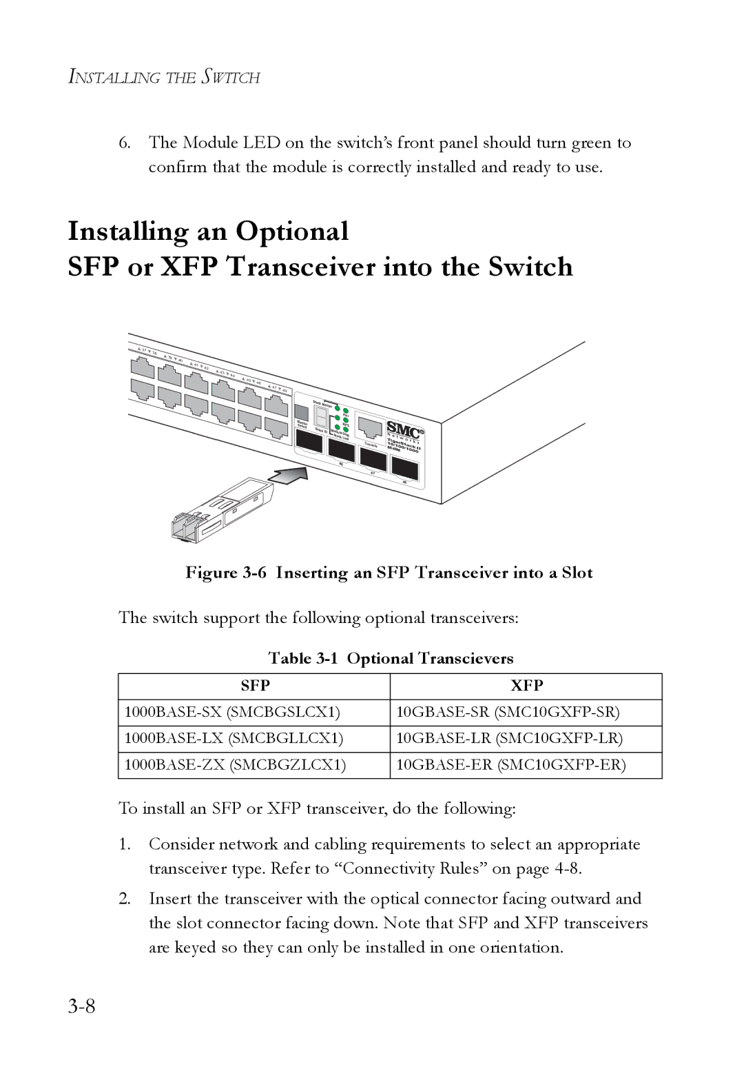
Figure 3-6 Inserting an SFP Transceiver into a Slot
The switch support the following optional transceivers:
Table 3-1 Optional Transcievers
SFP | XFP |
|
|
|
|
|
|
To install an SFP or XFP transceiver, do the following:
1.Consider network and cabling requirements to select an appropriate transceiver type. Refer to “Connectivity Rules” on page
2.Insert the transceiver with the optical connector facing outward and the slot connector facing down. Note that SFP and XFP transceivers are keyed so they can only be installed in one orientation.
