Instructions for the installer
3.4 Connection to gas
3.4.1 Connection with a rubber hose
Installation of the
Verify that all the following conditions are met:
•the hose is fixed to the hose connection with safety clamps;
•no part of the hose is in contact with the hot walls (max. 50 °C);
• the hose is not under traction or tension and has no tight curves or twists;
• the hose is not in contact with sharp objects or sharp corners;
• if the hose is not perfectly airtight and leaks gas, do not try and repair it: replace it with a new hose;
•verify that the hose is not beyond its life cycle (serigraphed on the hose itself).
CONNECTION USING RUBBER HOSES COMPLYING WITH THE CURRENT REGULATIONS IS ONLY PERMITTED IF THE HOSE CAN BE INSPECTED ALONG ITS ENTIRE LENGTH.
THE TIGHTENING TORQUE BETWEEN CONNECTIONS THAT INCORPORATE THE GASKET MUST NOT EXCEED 10NM
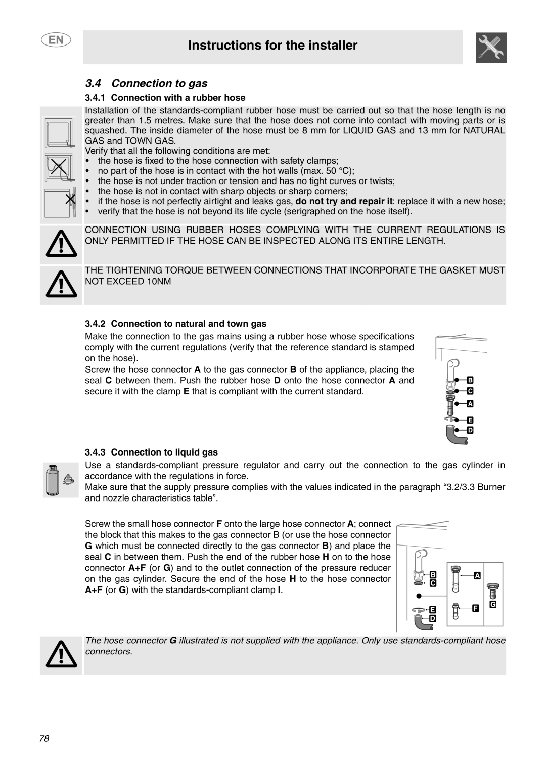
3.4.2 Connection to natural and town gas
Make the connection to the gas mains using a rubber hose whose specifications comply with the current regulations (verify that the reference standard is stamped on the hose).
Screw the hose connector A to the gas connector B of the appliance, placing the seal C between them. Push the rubber hose D onto the hose connector A and secure it with the clamp E that is compliant with the current standard.
3.4.3 Connection to liquid gas
Use a
Make sure that the supply pressure complies with the values indicated in the paragraph “3.2/3.3 Burner and nozzle characteristics table”.
Screw the small hose connector F onto the large hose connector A; connect the block that this makes to the gas connector B (or use the hose connector G which must be connected directly to the gas connector B) and place the seal C in between them. Push the end of the rubber hose H on to the hose connector A+F (or G) and to the outlet connection of the pressure reducer on the gas cylinder. Secure the end of the hose H to the hose connector A+F (or G) with the
The hose connector G illustrated is not supplied with the appliance. Only use
78