Instructions for the installer
5.2 Adjustment for LPG (Propane)
Check that the connection has been made as described in the “Gas connection” section.
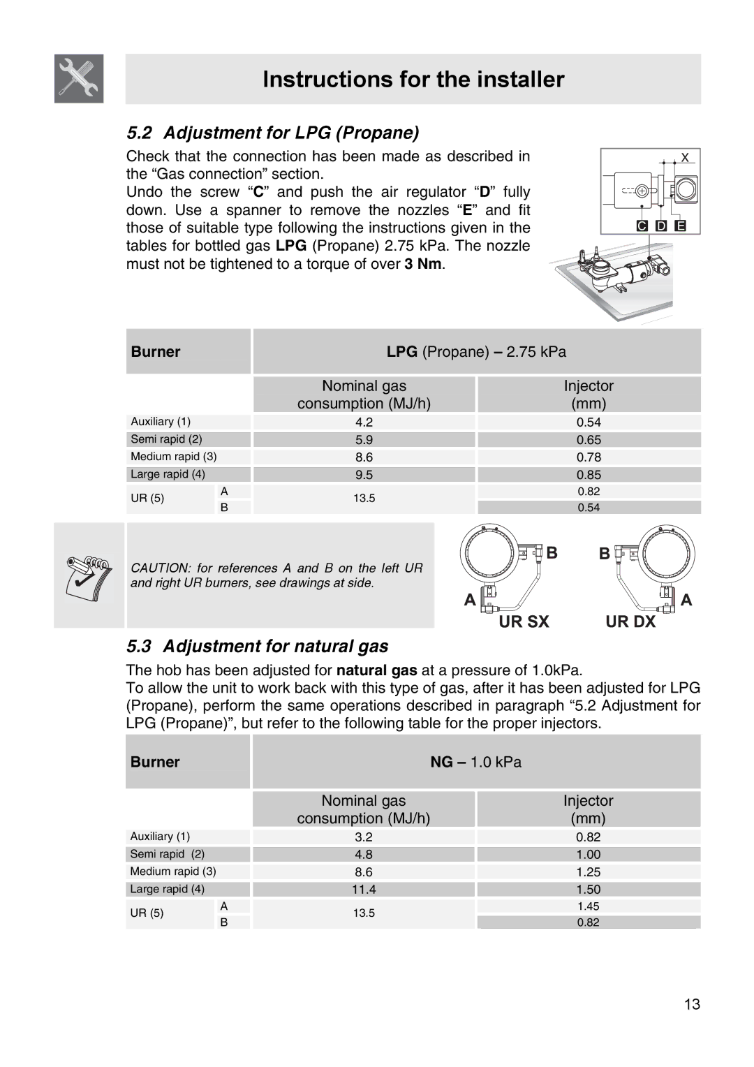
Undo the screw “C” and push the air regulator “D” fully down. Use a spanner to remove the nozzles “E” and fit those of suitable type following the instructions given in the tables for bottled gas LPG (Propane) 2.75 kPa. The nozzle must not be tightened to a torque of over 3 Nm.
Burner
Auxiliary (1) |
| |
Semi rapid (2) |
| |
Medium rapid (3) |
| |
Large rapid (4) |
| |
UR (5) | A | |
B | ||
|
LPG (Propane) – 2.75 kPa
| Nominal gas |
| Injector | |
|
| |||
| consumption (MJ/h) |
| (mm) | |
|
|
|
| |
4.2 |
| 0.54 | ||
|
|
| ||
| 5.9 |
| 0.65 | |
|
| |||
| 8.6 |
| 0.78 | |
|
| |||
| 9.5 |
| 0.85 | |
|
|
|
| |
| 13.5 |
| 0.82 | |
|
|
| ||
|
| 0.54 | ||
|
| |||
|
|
| ||
CAUTION: for references A and B on the left UR and right UR burners, see drawings at side.
5.3 Adjustment for natural gas
The hob has been adjusted for natural gas at a pressure of 1.0kPa.
To allow the unit to work back with this type of gas, after it has been adjusted for LPG (Propane), perform the same operations described in paragraph “5.2 Adjustment for LPG (Propane)”, but refer to the following table for the proper injectors.
Burner
Auxiliary (1) |
| |
Semi rapid | (2) | |
Medium rapid (3) | ||
Large rapid (4) | ||
UR (5) | A | |
B | ||
| ||
| NG – 1.0 kPa |
| ||
|
|
|
|
|
| Nominal gas |
|
| Injector |
| consumption (MJ/h) |
|
| (mm) |
|
|
|
|
|
3.2 |
|
| 0.82 | |
|
|
|
|
|
| 4.8 |
|
| 1.00 |
|
|
|
| |
| 8.6 |
|
| 1.25 |
|
|
|
| |
| 11.4 |
|
| 1.50 |
|
|
|
| 1.45 |
| 13.5 |
|
| |
|
|
| 0.82 | |
|
|
| ||
|
|
|
| |
13
