Smeg PGA75SC3, PGA75F3, PGA75FSC3 manual Attachment to support structure, flush-mounting model

Models: PGA75SC3 PGA75FSC3 PGA75F3

1 20
Download 20 pages 38.2 Kb
Page 5
Image 5
2.2Attachment to support structure, flush-mounting model

Instructions for the installer

2.2Attachment to support structure, flush-mounting model

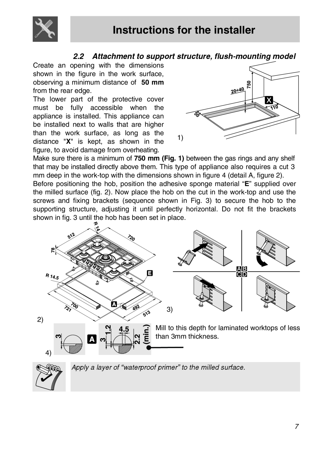
Create an opening with the dimensions

shown in the figure in the work surface, observing a minimum distance of 50 mm from the rear edge.

The lower part of the protective cover must be fully accessible when the appliance is installed. This appliance can

be installed next to walls that are higher

than the work surface, as long as the

1)

distance "X" is kept, as shown in the figure, to avoid damage from overheating.

Make sure there is a minimum of 750 mm (Fig. 1) between the gas rings and any shelf that may be installed directly above them. This type of appliance also requires a cut 3

mmdeep in the work-top with the dimensions shown in figure 4 (detail A, figure 2). Before positioning the hob, position the adhesive sponge material “E” supplied over the milled surface (fig. 2). Now place the hob on the cut in the work-top and use the screws and fixing brackets (sequence shown in Fig. 3) to secure the hob to the supporting structure, adjusting it until perfectly horizontal. Do not fit the brackets shown in fig. 3 until the hob has been set in place.

3)

2)

Mill to this depth for laminated worktops of less than 3mm thickness.

4)

Apply a layer of “waterproof primer” to the milled surface.

7

Page 5
Image 5
Smeg PGA75SC3, PGA75F3, PGA75FSC3 Attachment to support structure, flush-mounting model, Instructions for the installer