3. INSTRUCTIONS FOR THE INSTALLER
UNITS INTER-FITTING DIAGRAM
1.1 Hob-oven connection
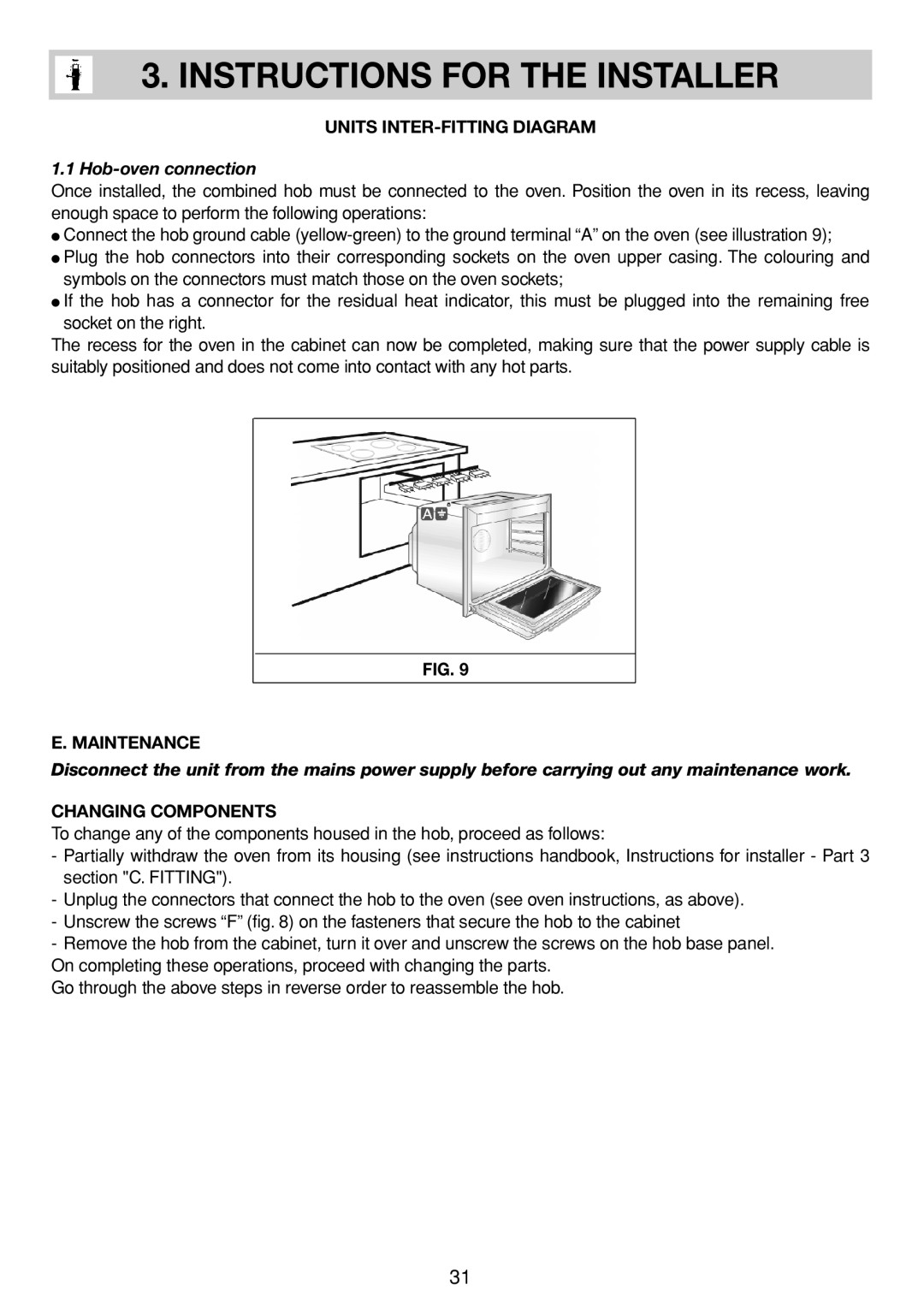
Once installed, the combined hob must be connected to the oven. Position the oven in its recess, leaving enough space to perform the following operations:
●Connect the hob ground cable
●Plug the hob connectors into their corresponding sockets on the oven upper casing. The colouring and symbols on the connectors must match those on the oven sockets;
●If the hob has a connector for the residual heat indicator, this must be plugged into the remaining free socket on the right.
The recess for the oven in the cabinet can now be completed, making sure that the power supply cable is suitably positioned and does not come into contact with any hot parts.
FIG. 9
E. MAINTENANCE
Disconnect the unit from the mains power supply before carrying out any maintenance work.
CHANGING COMPONENTS
To change any of the components housed in the hob, proceed as follows:
-Partially withdraw the oven from its housing (see instructions handbook, Instructions for installer - Part 3 section "C. FITTING").
-Unplug the connectors that connect the hob to the oven (see oven instructions, as above).
-Unscrew the screws “F” (fig. 8) on the fasteners that secure the hob to the cabinet
-Remove the hob from the cabinet, turn it over and unscrew the screws on the hob base panel.
On completing these operations, proceed with changing the parts.
Go through the above steps in reverse order to reassemble the hob.
31