Manuals
/
Smeg
/
Personal Care
/
Home Dialysis Equipment
Smeg
WO-01
manual
Models:
WO-01
1
19
23
23
Download
23 pages
5.25 Kb
16
17
18
19
20
21
22
23
Technical characteristics
Plumbing diagram
List of faults
Special adjustments
Hook UP J2 Green Power LED RES
Page 19
Image 19
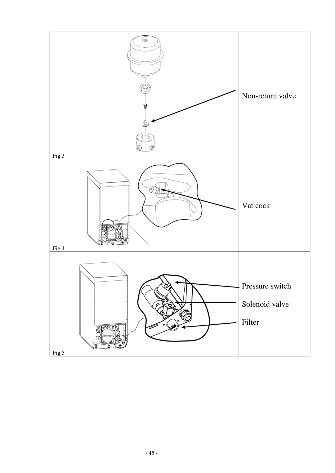
Non-return
valve
Fig.3
Vat cock
Fig.4
Pressure switch
Solenoid valve
Filter
Fig.5
- 45 -
Page 18
Page 20
Page 19
Image 19
Page 18
Page 20
Contents
WO-01
Page
Contents
General warnings
Technical characteristics
150-600 KPa Bar
Electrical hookup
Positioning
Plumbing hookup
Page
Delivery pump startup first startup
Pressurizing and starting up the unit
Replacing the membranes
Replacing the pre-filter
Inactivity
Special adjustments
Plumbing diagram
FIL
Wiring diagram
Hook UP J2 Green Power LED RES
List of faults
Osmosis-treated water not produced
Water production not conforming
Page
Electronic circuit board and programming
Page
Top
Page
Image
Contents