BELT TENSION ADJUSTMENT
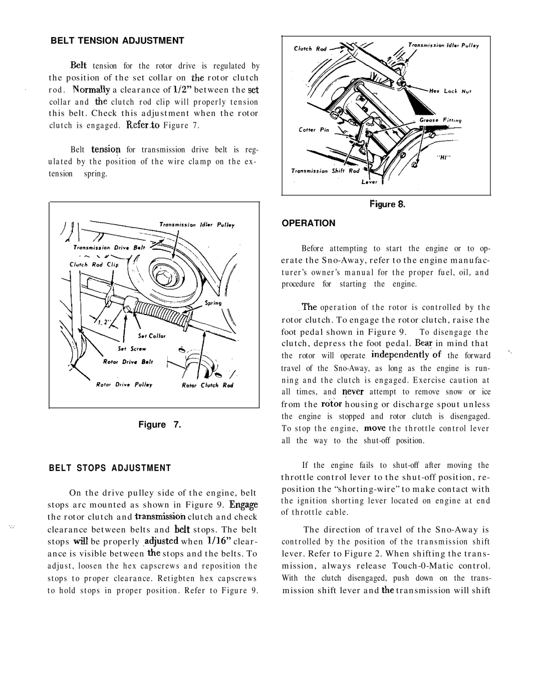
Belt tension for the rotor drive is regulated by the position of the set collar on ,the rotor clutch rod . NormaRy a clearance of 1iZ” between the set collar and the clutch rod clip will properly tension this belt. Check this adjustment when the rotor clutch is engaged. Refer30 Figure 7.
Belt tensiop for transmission drive belt is reg- ulated by the position of the wire clamp on the ex- tension spring.
Figure 7.
BELT STOPS ADJUSTMENT
On the drive pulley side of the engine, belt stops arc mounted as shown in Figure 9. Engage the rotor clutch and transmissioh clutch and check
OPERATION
Before attempting to start the engine or to op- erate the
The operation of the rotor is controlled by the rotor clutch. To engage the rotor clutch, raise the foot pedal shown in Figure 9. To disengage the clutch, depress the foot pedal. Bear in mind that
the rotor will operate independently~of the forward travel of the
If the engine fails to
j.
.,~Aclearance between belts and belt stops. The belt stops will be properly ,adjusted when l/16” clear- ance is visible between the stops and the belts. To adjust, loosen the hex capscrews and reposition the stops to proper clearance. Retigbten hex capscrews to hold stops in proper position. Refer to Figure 9.
The direction of travel of the