Figure 8. Upper UaSn
I![]() _
_
29.Align the steering wheel and push down onto shaft.
30.Reinstall capscrew (C, figure 7), flat washers, and locknuts to secure steering wheel. Torque nut to 10 ft. Ibs.
31.Reconnect throttle cable to engine and position under manifold capscrew and washer. Cable must be in original position for correct RPM setting. Tighten capscrew and place cable in
32.Push throttle control knob back on the lever. Tap knob with a hammer to seat.
33.Make sure the fuel lines are connected securely to the fuel filter with the clamps.
34.Install the rear
35.Raise rear of tractor up and rembve jackstand
36.Connect the battery cables - negative cable last.
37.Apply the decal to the right side of the switch.
38.This completes the installation.
I I
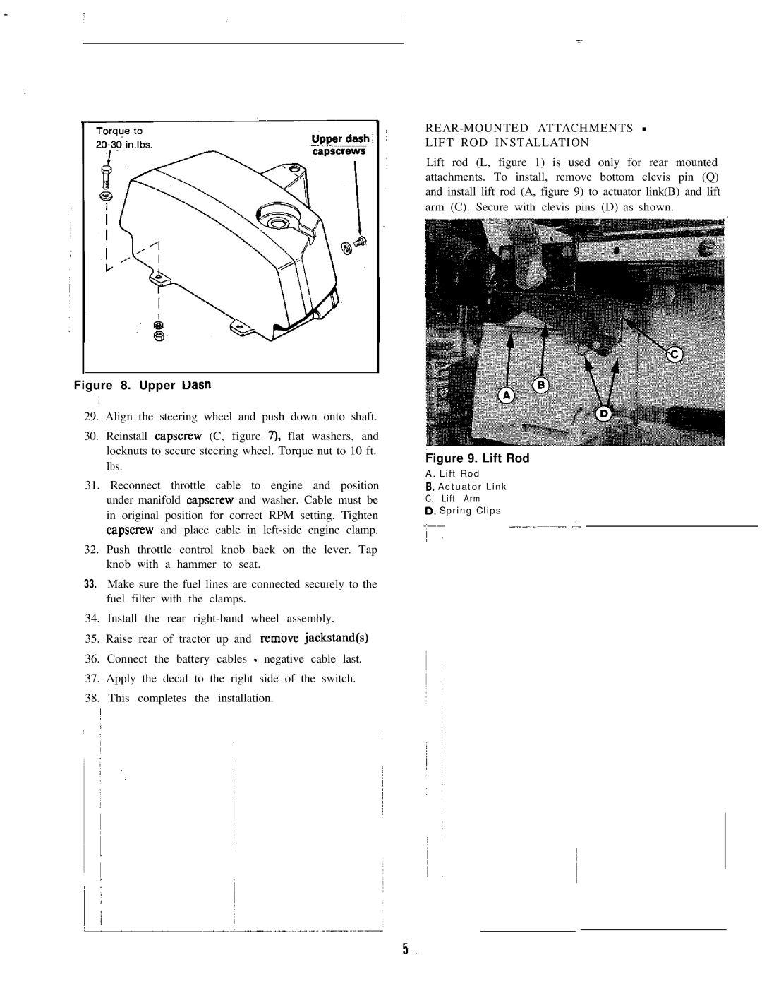
LIFT ROD INSTALLATION
Lift rod (L, figure 1) is used only for rear mounted attachments. To install, remove bottom clevis pin (Q) and install lift rod (A, figure 9) to actuator link(B) and lift arm (C). Secure with clevis pins (D) as shown.
Figure 9. Lift Rod
A. Lift Rod |
| |
6. | Actuator Link |
|
C. | Lift Arm | ~ |
|
| |
D. Spring Clips