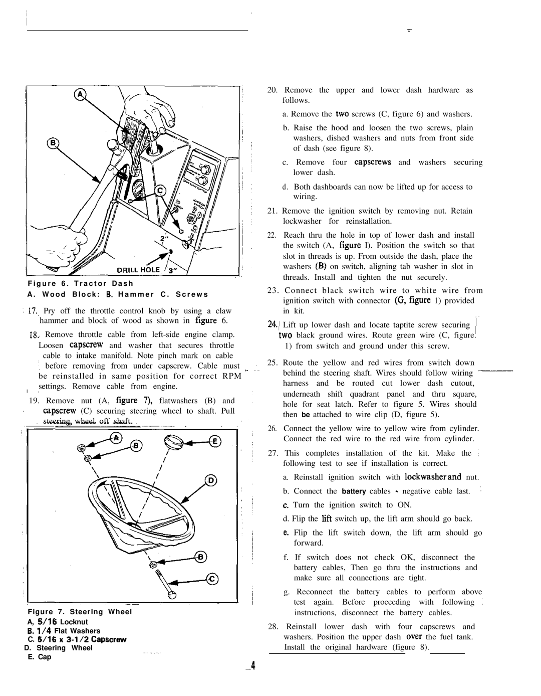
F i g u r e 6 . T r a c t o r D a s h
A . W o o d B l o c k : 6. H a m m e r C . S c r e w s
) 17., Pry off the throttle control knob by | using a claw | ~ |
hammer and block of wood as shown | in figure 6. |
lg., Remove throttle cable from
![]() ‘, before removing from under capscrew. Cable must ,~ ~~‘~~ be reinstalled in same position for correct RPM settings. Remove cable from engine.
‘, before removing from under capscrew. Cable must ,~ ~~‘~~ be reinstalled in same position for correct RPM settings. Remove cable from engine.
19. Remove nut (A, figure 7). flatwashers (B) and ![]() capscrew (C) securing steering wheel to shaft. Pull steering wheel off shaft.
capscrew (C) securing steering wheel to shaft. Pull steering wheel off shaft.
Figure 7. Steering Wheel
A, 5/16 Locknut
6. l/4 Flat Washers
C. 5116 x 3-l/2 Capscrew
D. Steering Wheel
E. Cap
20.Remove the upper and lower dash hardware as follows.
a.Remove the two screws (C, figure 6) and washers.
b. Raise the hood and loosen the two screws, plain : washers, dished washers and nuts from front side of dash (see figure 8).
c. Remove four capscrews and washers securing lower dash.
d. Both dashboards can now be lifted up for access to wiring.
21.Remove the ignition switch by removing nut. Retain lockwasher for reinstallation.
22.Reach thru the hole in top of lower dash and install the switch (A, figure I). Position the switch so that slot in threads is up. From outside the dash, place the washers (B) on switch, aligning tab washer in slot in threads. Install and tighten the nut securely.
23. Connect black switch wire to white wire from ignition switch with connector (C, figure 1) provided in kit.
24.) Lift up lower dash and locate taptite screw securing 1~
two black ground wires. Route green wire (C, | figure. |
1) from switch and ground under this screw. | ~ |
25.Route the yellow and red wires from switch down
behind the steering shaft. Wires should follow wiring
harness and be routed cut lower dash cutout, underneath shift quadrant panel and thru square, hole for seat latch. Refer to figure 5. Wires should then be attached to wire clip (D, figure 5).
26.Connect the yellow wire to yellow wire from cylinder. Connect the red wire to the red wire from cylinder.
27.This completes installation of the kit. Make the :![]() following test to see if installation is correct.
following test to see if installation is correct.
a.Reinstall ignition switch with lockwasherand nut.
b.Connect the battery cables - negative cable last. :![]()
c.Turn the ignition switch to ON.
d.Flip the lift switch up, the lift arm should go back.
e.Flip the lift switch down, the lift arm should go forward.
f.If switch does not check OK, disconnect the battery cables, Then go thru the instructions and ~ make sure all connections are tight.
g.Reconnect the battery cables to perform above test again. Before proceeding with following ![]() : instructions, disconnect the battery cables.
: instructions, disconnect the battery cables.
28.Reinstall lower dash with four capscrews and washers. Position the upper dash over the fuel tank. Install the original hardware (figure 8).