A WARNING
Before installing the kit or making any adjustments: disengage the PTO; set the parking brake; stop the engine and remove the key.
A WARNING
When disconnecting the battery cables, always disconnect the negative cable first. W h e n connecting cables, always connect the negative cable last. The positive terminal can easily be shorted to the frame with a tool if this is not done.
Do not touch any wires or electrical components such as the solenoid, unless the battery cables are
INSTALLATION
1.Park tractor on flat, level surface. Turn tractor off. Disengage PTO, and allow all moving parts to stop. Engage the parking brake.
,2. Disconnect the battery cables and position away from terminals.
gasoline may ignite. Insure clamps grip hose firmly
A WARNING
Handle gasoline with care. It is highly flammable. Use an approved gasoline container.
3.Drain the fuel tank as follows.
a.Place an approved gasoline container below the fuel filter.
b.Use a pliers to spread the fuel filter clamps and slide away from filter. Do not spread more than necessary.
~c. Pull hoses off filter and allow gasoline to drain into container.
4.Raise rear
Remove rear
Remove tive capscrews from wheel assembly and secure kit hub assembly (0, figure 1) to wheel. Do not install on tractor.
Prepare template (provided on last page) by cutting out all dashed areas. Use this template to drill five 1 l/32” holes in wrapper.
Install rear actuator bracket (X, figure 1 or A, figure
2)with two capscrews (T, figure l), spacers (U), lockwashers (D), and nuts (R). Install bolts from outside in, putting spacers between bracket and wrapper. Lockwashers and nuts are installed on inside of wrapper. Do not install the
(W) at this time.
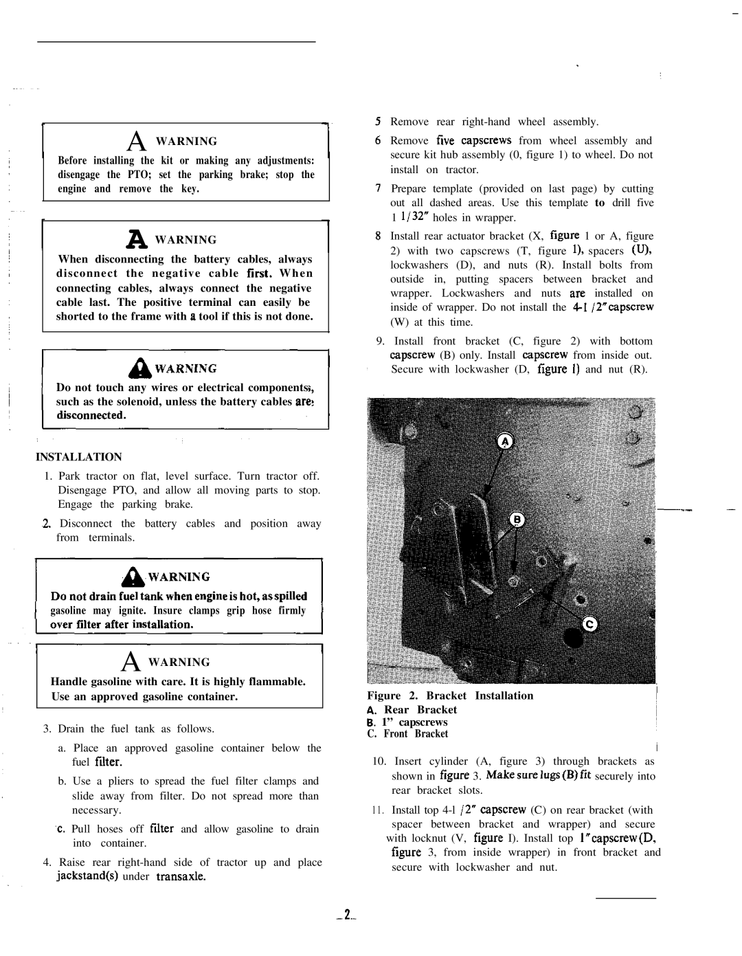
9.Install front bracket (C, figure 2) with bottom capscrew (B) only. Install capscrew from inside out.
,Secure with lockwasher (D, figure 1) and nut (R).
.-
Figure 2. Bracket Installation
A. Rear Bracket
6.1” capscrews C. Front Bracket
10.Insert cylinder (A, figure 3) through brackets as shown in figure 3. Makesurelugs(B)fit securely into rear bracket slots.
11 . Install top
with locknut (V, figure I). Install top l”capscrew(D, figure 3, from inside wrapper) in front bracket and secure with lockwasher and nut.