Installation Instructions | Hitch & Tube Group |
2. Connect the inner hitch (B, Figure 3) to the cross bar |
hitch (C) using |
C![]()
![]() A
A
3. | Connect the cross bar hitch (C) to the brackets (E) |
| using |
| locknuts (A). |
4. | Tighten all hardware. |
DISCHARGE TUBE ASSEMBLY
1. | Connect the flexible hose (F, Figure 4) and clear |
| plastic discharge tube (B). The two should overlap |
| by approximately 2”. |
2. | Secure the tubes using truss head screws (E), wash- |
E
B
D
A
E
D
ers (D), and locknuts (C). Insert the screws from the |
inside out and poke them through the flexible hose. |
3. Insert the upper end of the clear tube into the cart |
sleeve. Slide the flex hose (F) over the turbo (H) and |
secure with the large hose clamp (G). The hose |
should overlap the turbo discharge by |
The clamp screw should be positioned to the inside |
as shown to prevent accidental impact and removal |
of the clamp. |
Check that the upper end of the clear tube (B, Figure |
4) is not contacting the top of the collector cover. If |
necessary, cut off the clear tube flush with the con- |
necting sleeve (See Wide Body Cart Operators |
Manual). |
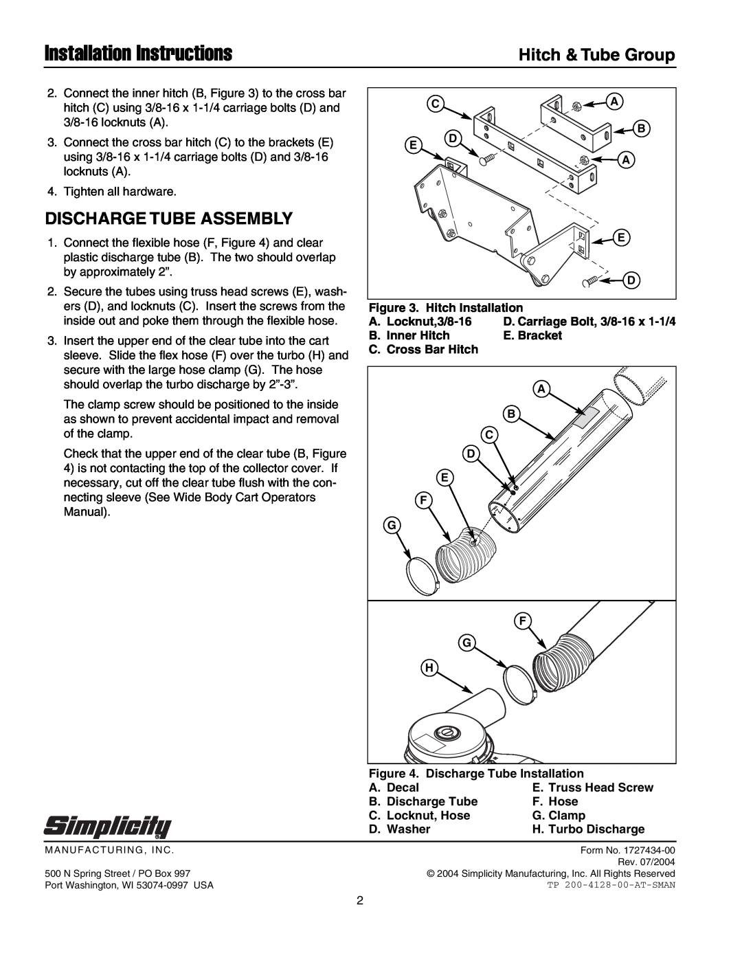
Figure 3. Hitch Installation
A.
B. Inner Hitch E. Bracket C. Cross Bar Hitch
A |
B |
C |
D |
E |
F |
G |
F |
G |
H |
Figure 4. Discharge Tube Installation | |
A. Decal | E. Truss Head Screw |
B. Discharge Tube | F. Hose |
C. Locknut, Hose | G. Clamp |
D. Washer | H. Turbo Discharge |
MANUFACTURING, INC . | Form No. |
| Rev. 07/2004 |
500 N Spring Street / PO Box 997 | © 2004 Simplicity Manufacturing, Inc. All Rights Reserved |
Port Washington, WI | TP |
2