XDV Direct Vent Gas Fireplace
Vertical Sidewall Installation
Twist Lock Pipe
STEP 1
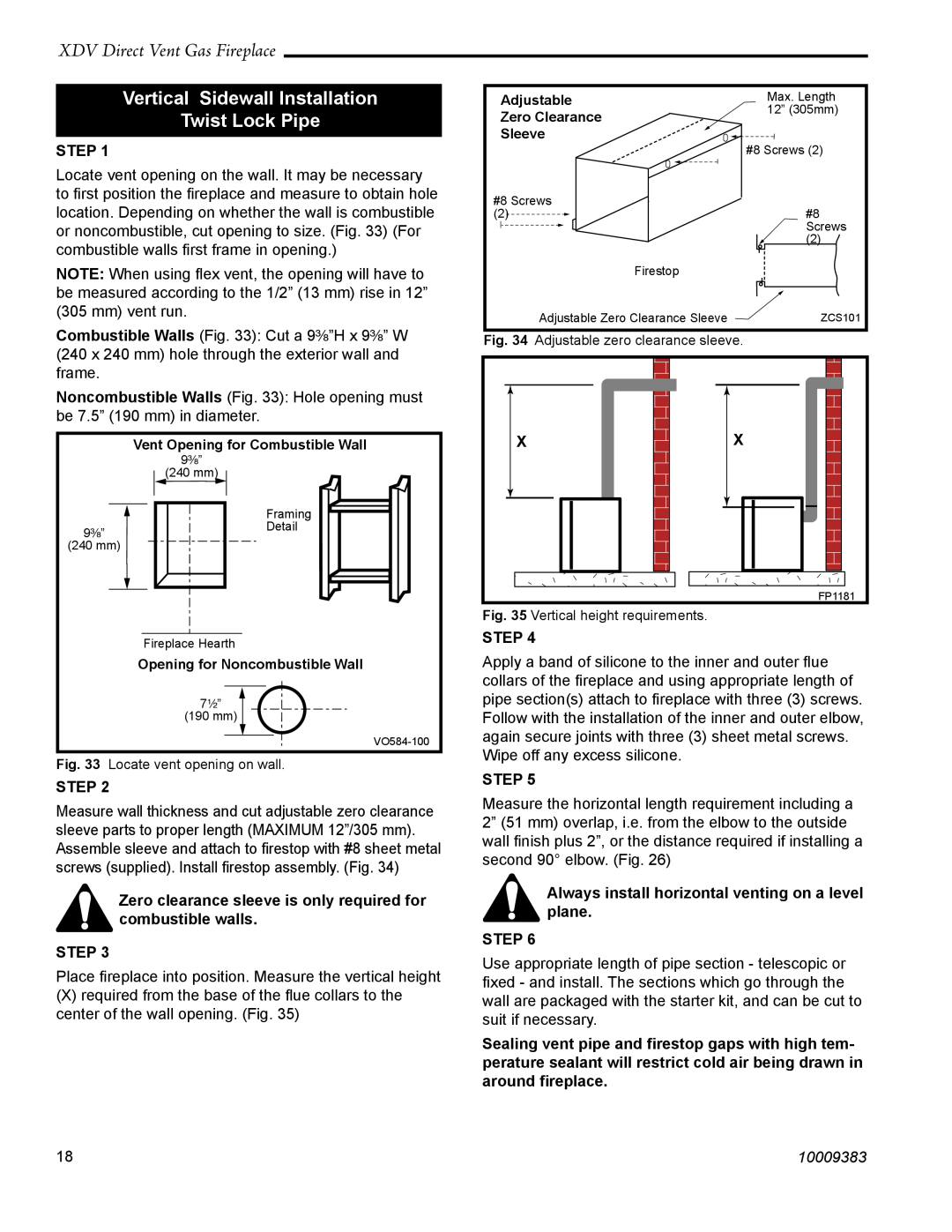
Locate vent opening on the wall. It may be necessary to first position the fireplace and measure to obtain hole location. Depending on whether the wall is combustible or noncombustible, cut opening to size. (Fig. 33) (For combustible walls first frame in opening.)
NOTE: When using flex vent, the opening will have to be measured according to the 1/2” (13 mm) rise in 12” (305 mm) vent run.
Combustible Walls (Fig. 33): Cut a 9³⁄₈”H x 9³⁄₈” W (240 x 240 mm) hole through the exterior wall and frame.
Noncombustible Walls (Fig. 33): Hole opening must be 7.5” (190 mm) in diameter.
| Vent Opening for Combustible Wall |
| 9³⁄₈” |
| (240 mm) |
| Framing |
9³⁄₈” | Detail |
| |
(240 mm) | |
| Fireplace Hearth |
| Opening for Noncombustible Wall |
| 7¹⁄₂” |
| (190 mm) |
| |
Fig. 33 | Locate vent opening on wall. |
STEP 2
Measure wall thickness and cut adjustable zero clearance sleeve parts to proper length (MAXIMUM 12”/305 mm). Assemble sleeve and attach to firestop with #8 sheet metal screws (supplied). Install firestop assembly. (Fig. 34)
Zero clearance sleeve is only required for combustible walls.
STEP 3
Place fireplace into position. Measure the vertical height
(X)required from the base of the flue collars to the center of the wall opening. (Fig. 35)
Adjustable | Max. Length |
Zero Clearance | 12” (305mm) |
| |
Sleeve |
|
| #8 Screws (2) |
#8 Screws |
|
(2) | #8 |
| Screws |
| (2) |
Firestop |
|
Adjustable Zero Clearance Sleeve | ZCS101 |
Fig. 34 Adjustable zero clearance sleeve. |
|
X | X |
FP1181
Fig. 35 Vertical height requirements.
STEP 4
Apply a band of silicone to the inner and outer flue collars of the fireplace and using appropriate length of pipe section(s) attach to fireplace with three (3) screws. Follow with the installation of the inner and outer elbow, again secure joints with three (3) sheet metal screws. Wipe off any excess silicone.
STEP 5
Measure the horizontal length requirement including a 2” (51 mm) overlap, i.e. from the elbow to the outside wall finish plus 2”, or the distance required if installing a second 90° elbow. (Fig. 26)
Always install horizontal venting on a level plane.
STEP 6
Use appropriate length of pipe section - telescopic or fixed - and install. The sections which go through the wall are packaged with the starter kit, and can be cut to suit if necessary.
Sealing vent pipe and firestop gaps with high tem- perature sealant will restrict cold air being drawn in around fireplace.
18 | 10009383 |