XDV Direct Vent Gas Fireplace
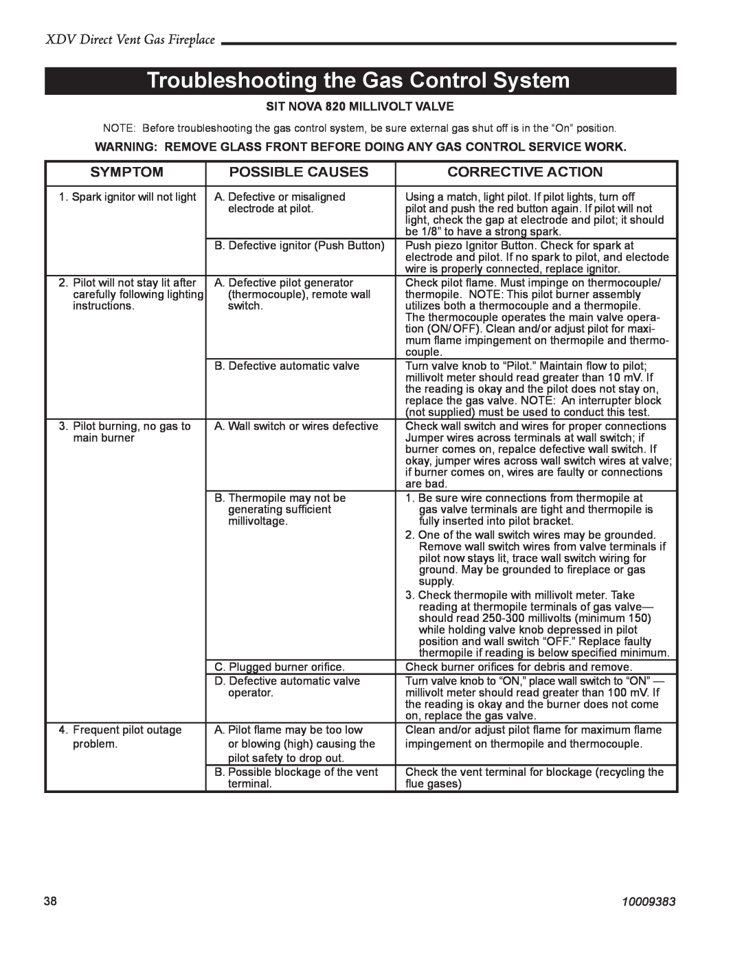
Troubleshooting the Gas Control System
SIT NOVA 820 MILLIVOLT VALVE
NOTE: Before troubleshooting the gas control system, be sure external gas shut off is in the “On” position.
WARNING: REMOVE GLASS FRONT BEFORE DOING ANY GAS CONTROL SERVICE WORK.
SYMPTOM | POSSIBLE CAUSES | CORRECTIVE ACTION |
|
|
|
1. Spark ignitor will not light | A. Defective or misaligned | Using a match, light pilot. If pilot lights, turn off |
| electrode at pilot. | pilot and push the red button again. If pilot will not |
|
| light, check the gap at electrode and pilot; it should |
|
| be 1/8” to have a strong spark. |
| B. Defective ignitor (Push Button) | Push piezo Ignitor Button. Check for spark at |
|
| electrode and pilot. If no spark to pilot, and electode |
|
| wire is properly connected, replace ignitor. |
2. Pilot will not stay lit after | A. Defective pilot generator | Check pilot flame. Must impinge on thermocouple/ |
carefully following lighting | (thermocouple), remote wall | thermopile. NOTE: This pilot burner assembly |
instructions. | switch. | utilizes both a thermocouple and a thermopile. |
|
| The thermocouple operates the main valve opera- |
|
| tion (ON/OFF). Clean and/or adjust pilot for maxi- |
|
| mum flame impingement on thermopile and thermo- |
|
| couple. |
| B. Defective automatic valve | Turn valve knob to “Pilot.” Maintain flow to pilot; |
|
| millivolt meter should read greater than 10 mV. If |
|
| the reading is okay and the pilot does not stay on, |
|
| replace the gas valve. NOTE: An interrupter block |
|
| (not supplied) must be used to conduct this test. |
3. Pilot burning, no gas to | A. Wall switch or wires defective | Check wall switch and wires for proper connections |
main burner |
| Jumper wires across terminals at wall switch; if |
|
| burner comes on, repalce defective wall switch. If |
|
| okay, jumper wires across wall switch wires at valve; |
|
| if burner comes on, wires are faulty or connections |
|
| are bad. |
| B. Thermopile may not be | 1. Be sure wire connections from thermopile at |
| generating sufficient | gas valve terminals are tight and thermopile is |
| millivoltage. | fully inserted into pilot bracket. |
|
| 2. One of the wall switch wires may be grounded. |
|
| Remove wall switch wires from valve terminals if |
|
| pilot now stays lit, trace wall switch wiring for |
|
| ground. May be grounded to fireplace or gas |
|
| supply. |
|
| 3. Check thermopile with millivolt meter. Take |
|
| reading at thermopile terminals of gas valve— |
|
| should read |
|
| while holding valve knob depressed in pilot |
|
| position and wall switch “OFF.” Replace faulty |
|
| thermopile if reading is below specified minimum. |
| C. Plugged burner orifice. | Check burner orifices for debris and remove. |
| D. Defective automatic valve | Turn valve knob to “ON,” place wall switch to “ON” — |
| operator. | millivolt meter should read greater than 100 mV. If |
|
| the reading is okay and the burner does not come |
|
| on, replace the gas valve. |
4. Frequent pilot outage | A. Pilot flame may be too low | Clean and/or adjust pilot flame for maximum flame |
problem. | or blowing (high) causing the | impingement on thermopile and thermocouple. |
| pilot safety to drop out. |
|
| B. Possible blockage of the vent | Check the vent terminal for blockage (recycling the |
| terminal. | flue gases) |
38 | 10009383 |
