Top Vent Application
Restrictor Plate
When the 33XDV or 36XDV models are installed as top vent fireplaces with a minimum 12” (305 mm) rise, the restrictor plate must be installed to give better flame appearance.
This restrictor plate is shipped with the 33/36XDV and is located below the access control panel.
33XDV Restrictor Plate Installation
1.Remove rear log bracket located behind the burner panel.
2.Install the restrictor plate with the rear log using ex- isting mounting holes and
3.Install rear log bracket assembly by reversing Step 1.
4.Install log set, ember materials, lava rock. Refer to log set installation section.
36XDV Restrictor Plate Installation
1.Remover rear log bracket located behind the burner panel.
2.Replace the deflector rear log bracket with the restrictor plate to the rear log bracket using existing mounting holes and screws. (Fig. 16) Discard deflec- tor.
3.Install rear log bracket assembly by reversing Step 1.
4.Install log set, ember materials, lava rock. Refer to log set installation section.
XDV Direct Vent Gas Fireplace
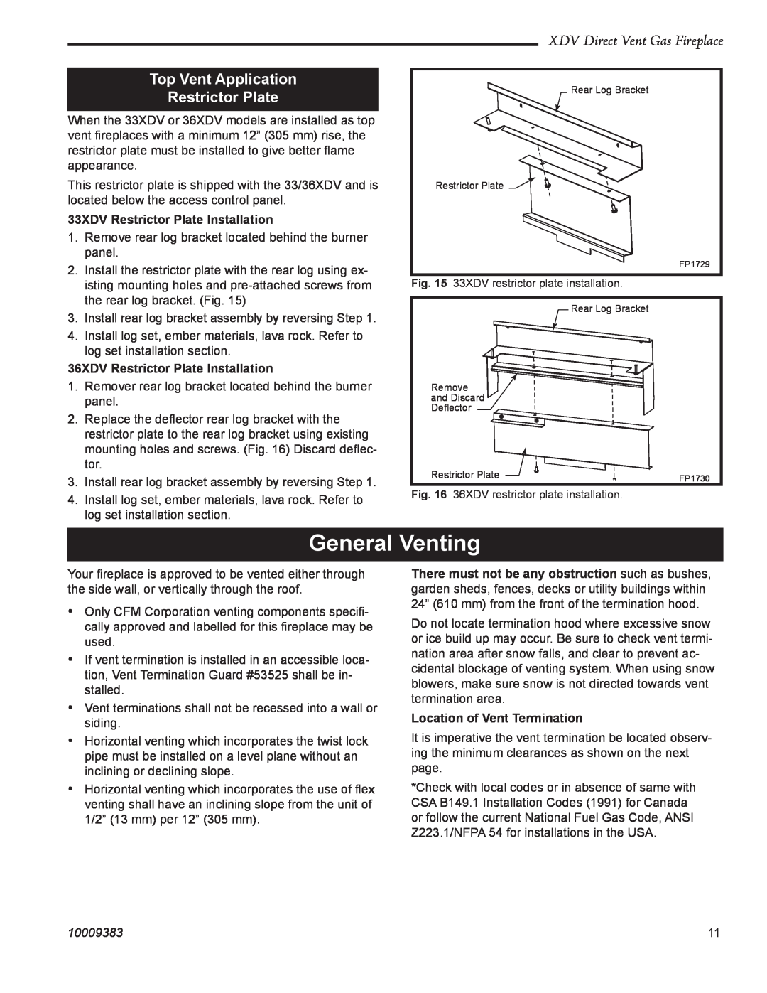
Rear Log Bracket
Restrictor Plate ![]()
FP1729
Fig. 15 33XDV restrictor plate installation.
Rear Log Bracket
Remove
and Discard ![]()
Deflector
Restrictor Plate | FP1730 |
|
Fig. 16 36XDV restrictor plate installation.
General Venting
Your fireplace is approved to be vented either through the side wall, or vertically through the roof.
•Only CFM Corporation venting components specifi- cally approved and labelled for this fireplace may be used.
•If vent termination is installed in an accessible loca- tion, Vent Termination Guard #53525 shall be in- stalled.
•Vent terminations shall not be recessed into a wall or siding.
•Horizontal venting which incorporates the twist lock pipe must be installed on a level plane without an inclining or declining slope.
•Horizontal venting which incorporates the use of flex venting shall have an inclining slope from the unit of 1/2” (13 mm) per 12” (305 mm).
There must not be any obstruction such as bushes, garden sheds, fences, decks or utility buildings within 24” (610 mm) from the front of the termination hood.
Do not locate termination hood where excessive snow or ice build up may occur. Be sure to check vent termi- nation area after snow falls, and clear to prevent ac- cidental blockage of venting system. When using snow blowers, make sure snow is not directed towards vent termination area.
Location of Vent Termination
It is imperative the vent termination be located observ- ing the minimum clearances as shown on the next page.
*Check with local codes or in absence of same with CSA B149.1 Installation Codes (1991) for Canada or follow the current National Fuel Gas Code, ANSI Z223.1/NFPA 54 for installations in the USA.
10009383 | 11 |