XDV Direct Vent Gas Fireplace
Remote Controls
Optional remote control units are available to control dif- ferent functions of the appliance. (For use on R Models)
| Section A | Heat |
Heat Shield |
| |
| Shield |
Model |
| Functions Controlled |
| ||
RC1 |
| ON/OFF |
|
| |
RC2 |
| ON/OFF and Temperature |
| ||
IMTFK | Wall mounted thermostat control | ||||
|
|
| |||
| Ceramic Refractory Panels |
| |||
|
|
|
| ||
Unit |
| Kit Model and Finishings |
| ||
Sandstone | Red | Black | Grey | ||
33XDV |
| GAHC3I0 | GAFC3I0 | GABC3I0 | GAGC3I0 |
36XDV |
| GAHC3J0 | GAFC3J0 | GABC3J0 | GAGC3J0 |
39XDV | GAHC3K0 | GAFC3K0 | GABC3K0 GAGC3K0 | ||
Take care when handling the refractory panels as they are fragile until held in place and supported.
Installation Instructions
1. | Remove window frame assembly and logs. |
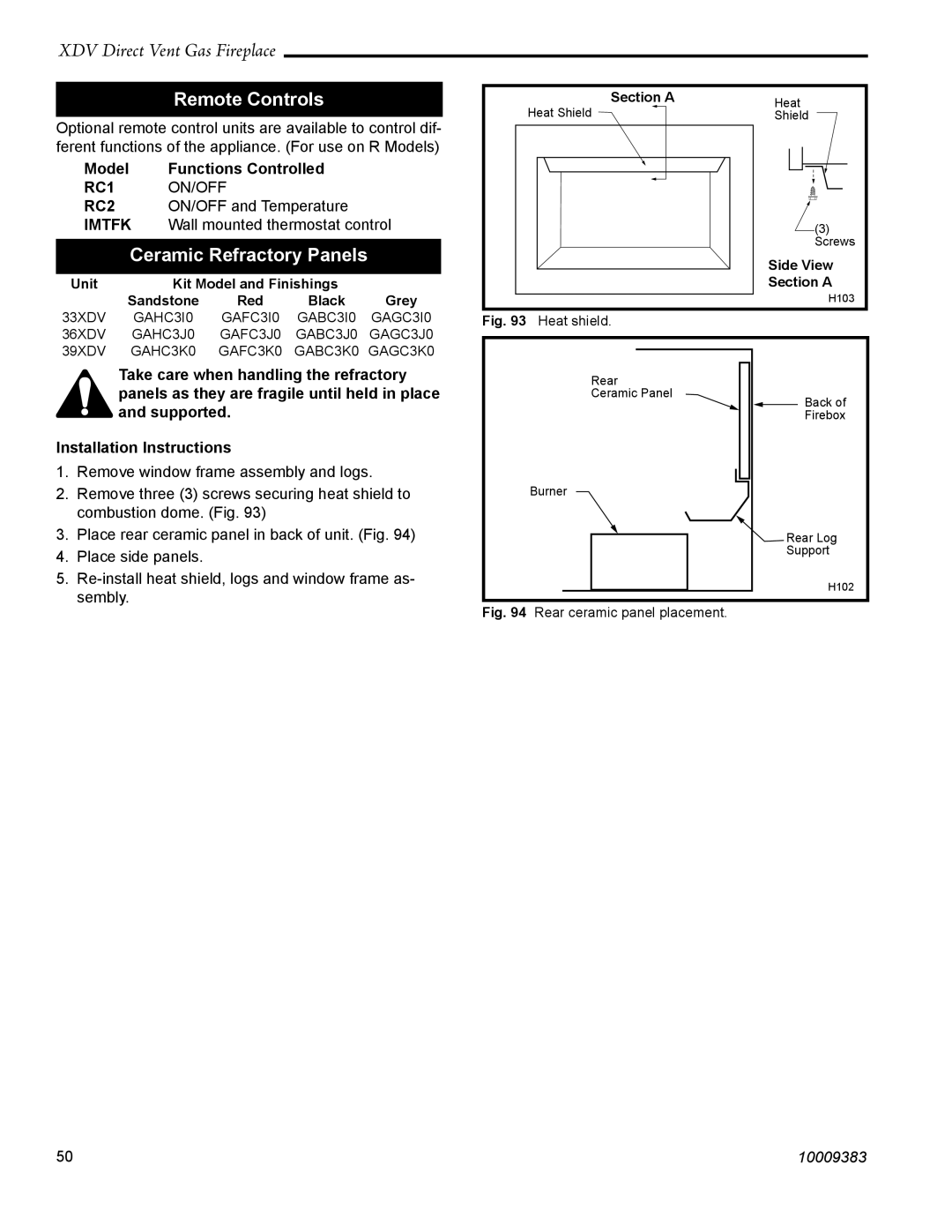
2. | Remove three (3) screws securing heat shield to |
| combustion dome. (Fig. 93) |
Fig. 93 Heat shield.
Rear
Ceramic Panel
Burner
![]() (3)
(3)
Screws
Side View
Section A
H103
![]() Back of Firebox
Back of Firebox
3. | Place rear ceramic panel in back of unit. (Fig. 94) |
4. | Place side panels. |
5. | |
| sembly. |
![]() Rear Log
Rear Log
Support
H102
Fig. 94 Rear ceramic panel placement.
50 | 10009383 |
