The
To connect the
1.Unscrew the retaining screw from the
2.Remove the front cover of the
3.Remove the plug socket assembly from the
4.Feed the supply line in through the
5.Connect the black wire of the power supply line to the brass screw (polarized) of the socket assembly.
6.Connect the white wire of the power line to the chrome screw of the socket assembly.
7.Connect the ground wire of the supply line to the green screw of the socket assembly.
8.Refit the socket assembly back into the electrical box and replace the cover plate. Secure the cable with the clamp on the outside of the
XDV Direct Vent Gas Fireplace
INSIDE
Electrical Box
![]()
![]() FRONTOFUNIT
FRONTOFUNIT 
OUTSIDE
| OF | UNIT | |
FRONT | FP580 | ||
| |||
|
|
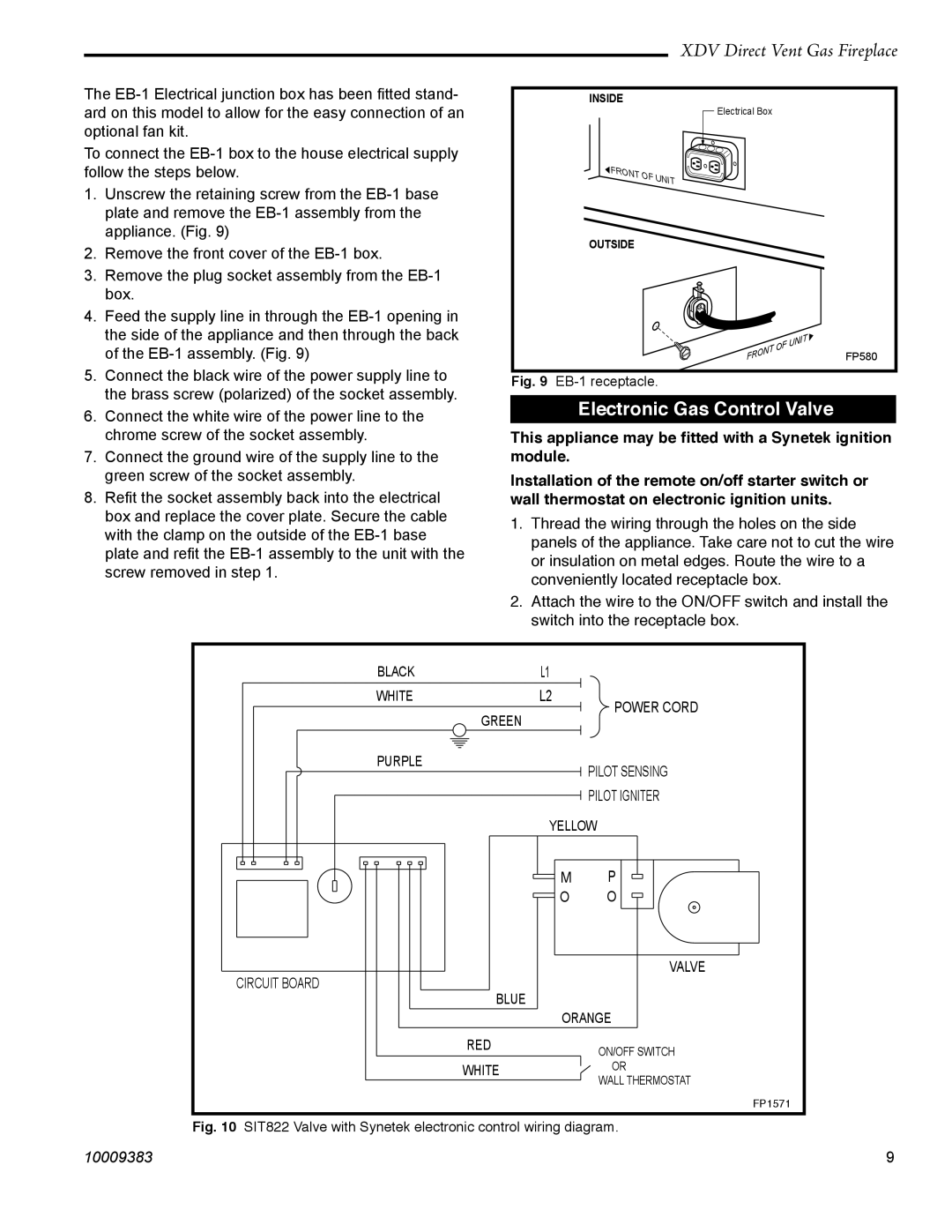
Fig. 9
Electronic Gas Control Valve
This appliance may be fitted with a Synetek ignition module.
Installation of the remote on/off starter switch or wall thermostat on electronic ignition units.
1.Thread the wiring through the holes on the side panels of the appliance. Take care not to cut the wire or insulation on metal edges. Route the wire to a conveniently located receptacle box.
2.Attach the wire to the ON/OFF switch and install the
switch into the receptacle box.
| BLACK |
|
|
|
| L1 |
|
|
| |||
| WHITE |
|
|
|
| L2 |
|
| POWER CORD | |||
|
|
| ||||||||||
|
|
|
|
|
|
|
|
| GREEN |
|
| |
|
|
|
|
|
|
|
|
|
|
|
| |
|
|
|
|
|
|
|
|
|
|
|
|
|
|
|
|
|
|
|
|
|
|
|
|
|
|
|
|
|
|
|
|
|
|
|
|
|
|
|
|
|
|
|
|
|
|
|
|
|
|
|
|
PURPLE
PILOT SENSING PILOT IGNITER
CIRCUIT BOARD
YELLOW
|
|
|
|
|
|
|
|
|
|
|
|
|
|
|
|
|
|
|
|
|
|
|
|
|
|
|
|
|
| M |
| P |
|
|
|
| |
|
|
|
|
|
|
|
|
|
|
|
|
|
|
|
|
| ||
|
|
|
|
|
|
|
|
|
|
|
|
|
|
|
| |||
|
|
|
|
|
|
|
|
|
|
| O |
| O |
|
|
|
| |
|
|
|
|
|
|
|
|
|
|
|
|
|
|
|
| |||
|
|
|
|
|
|
|
|
|
|
|
|
|
|
|
|
|
|
|
|
|
|
|
|
|
|
|
|
|
|
|
|
|
|
|
|
|
|
|
|
|
|
|
|
|
|
|
|
|
|
|
|
|
|
|
|
|
|
|
|
|
|
|
|
|
|
|
|
|
|
|
|
| VALVE |
| |
|
|
|
|
|
|
| BLUE |
|
|
|
|
|
|
|
|
| ||
|
|
|
|
|
|
|
|
|
|
|
|
|
|
|
| |||
|
|
|
|
|
|
|
|
|
|
| ORANGE |
|
| |||||
|
|
|
|
|
| RED |
| ON/OFF SWITCH |
| |||||||||
|
|
|
|
|
|
|
|
|
|
|
|
|
| |||||
|
|
|
|
|
| WHITE |
| OR |
| |||||||||
|
|
| ||||||||||||||||
|
| WALL THERMOSTAT |
| |||||||||||||||
|
|
|
|
|
|
|
|
|
|
|
|
|
| |||||
FP1571
Fig. 10 SIT822 Valve with Synetek electronic control wiring diagram.
10009383 | 9 |