Section 3 – MAINTENANCE
WARNING
DO NOT attempt any adjustments, maintenance, service or repairs with the engine running. Stop engine. Stop blade. Engage parking brake. Remove key. Remove spark plug wire from spark plug and secure away from plug. Engine and components are HOT. Avoid serious burns, allow all parts to cool before working on machine. Fuel Filler Cap and Vent must be closed securely to prevent fuel spillage.
3.4SERVICE - ANNUALLY 3.4.1. ENGINE
1.Perform all maintenance as specified in “MAINTENANCE SCHEDULE” Section of this manual.
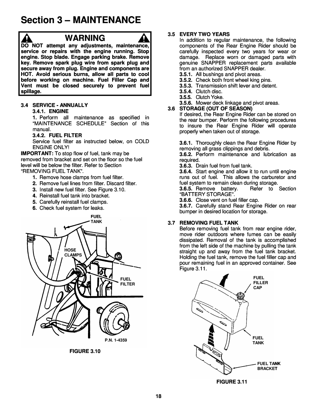
3.4.2. FUEL FILTER
Service fuel filter as instructed below, on COLD ENGINE ONLY!
IMPORTANT: To stop flow of fuel, tank may be removed from bracket and set on the floor so the fuel level will be below the filter. Refer to Section
“REMOVING FUEL TANK”.
1.Remove hose clamps from fuel filter.
2.Remove fuel lines from filter. Discard filter.
3.Install new fuel filter. See Figure 3.10.
4.Reinstall fuel tank into bracket.
5.Carefully reinstall fuel clamps.
6.Check fuel system for leaks.
FUEL
TANK
HOSE
CLAMPS
FUEL
FILTER
P.N.
FIGURE 3.10
3.5EVERY TWO YEARS
In addition to regular maintenance, the following components of the Rear Engine Rider should be carefully inspected every two years for wear or damage. Replace worn or damaged parts with genuine SNAPPER replacement parts available from an authorized SNAPPER dealer.
3.5.1.All bushings and pivot areas.
3.5.2.Check both front wheel king pins.
3.5.3.Transmission shift lever and detent.
3.5.4.Clutch disc.
3.5.5.Clutch Yoke.
3.5.6.Mower deck linkage and pivot areas.
3.6STORAGE (OUT OF SEASON)
If desired, the Rear Engine Rider can be stored on the rear bumper. Perform the following procedures to insure the Rear Engine Rider will operate properly when taken out of storage.
3.6.1.Thoroughly clean the Rear Engine Rider by removing all grass clippings and debris.
3.6.2.Perform maintenance and lubrication as required.
3.6.3.Drain fuel from fuel tank.
3.6.4.Start engine and allow it to run until engine runs out of fuel. This allows the carburetor and fuel system to remain clean during storage.
3.6.5.Remove battery. Refer to Section
“BATTERY STORAGE”.
3.6.6.Close vent on fuel filler cap.
3.6.7.Carefully stand Rear Engine Rider on rear bumper in desired location for storage.
3.7REMOVING FUEL TANK
Before removing fuel tank from rear engine rider, move rider outdoors where fumes can be easily dissipated. Removal of the tank is accomplished from the left side of the machine by pulling the tank straight up and away from the fuel tank bracket. Holding the fuel tank, remove the fuel filler cap and pour remaining fuel in an approved container. See Figure 3.11.
FUEL
FILLER
CAP
FUEL
TANK
FUEL TANK
BRACKET
FIGURE 3.11
18