Sharpening the Mower Blade
![]() CAUTION
CAUTION
Avoid injury! Mower blades are sharp.
•Always wear gloves when handling the mower blades.
•Always wear safety eye protection when grinding.
1.Sharpen the mower blades with grinder, hand file, or electric blade sharpener.
2.Sharpen the mower blade by removing an equal amount of material from each end of the mower blade.
3.Keep the original bevel (A, Figure 28) when grinding. DO NOT change the mower blade bevel.
4.The mower blade should have a maximum 1/64” (0,40 mm) cutting edge (B) or less.
5.Balance the mower blades before installing.
Balancing the Mower Blades
![]() CAUTION
CAUTION
Avoid injury! Keep mower blades balanced.
•An unbalanced mower blade can create excessive vibration and damage the unit or cause mower blade failure.
1.Clean the mower blade to remove any dried grass or other debris.
2.See Figure 29. Put the mower blade on a nail in a vise and turn the mower blade to the horizontal position.
3.Check the balance of the mower blade. If either end of the mower blade moves downward, sharpen the heavy end until the mower blade is balanced. See Sharpening the Mower Blades for proper sharpening instructions.
4.Repeat the process until the mower blade remains in the horizontal position.
Reinstalling the Mower Blades
![]() WARNING
WARNING
For your personal safety, each mower blade mounting bolt must be installed with a hex/spline washer and spring washer, then securely tightened. Torque mower blade mounting bolt to
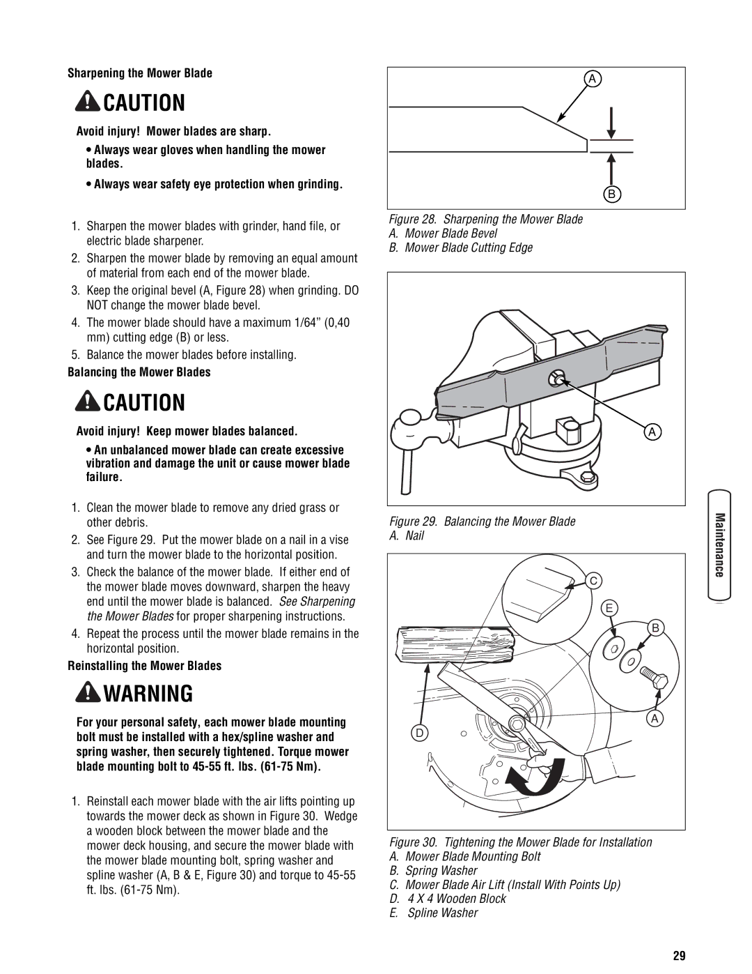
1.Reinstall each mower blade with the air lifts pointing up towards the mower deck as shown in Figure 30. Wedge a wooden block between the mower blade and the mower deck housing, and secure the mower blade with the mower blade mounting bolt, spring washer and spline washer (A, B & E, Figure 30) and torque to
A |
B |
Figure 28. Sharpening the Mower Blade
A.Mower Blade Bevel
B.Mower Blade Cutting Edge
A |
Figure 29. Balancing the Mower Blade
A. Nail
E |
B |
A |
D |
Figure 30. Tightening the Mower Blade for Installation
A.Mower Blade Mounting Bolt
B.Spring Washer
C.Mower Blade Air Lift (Install With Points Up)
D.4 X 4 Wooden Block
E.Spline Washer
29