! | Important Operator Safety Instructions | ! |
Safety
Operating Safety
Congratulations on purchasing a
Do not operate this machine unless you have been trained. Reading and understanding this operator’s manual is a way to train yourself.
Power equipment is only as safe as the operator. If it is misused, or not properly maintained, it can be dangerous! Remember, you are responsible for your safety and that of those around you.
Use common sense, and think through what you are doing. If you are not sure that the task you are about to perform can be safely done with the equipment you have chosen, ask a professional: contact your local authorized dealer.
Read the Manual
The operator’s manual contains important safety information you need to be aware of BEFORE you operate your unit as well as DURING operation.
Safe operating techniques, an explanation of the product’s features and controls, and maintenance information is included to help you get the most out of your equipment investment.
Be sure to completely read the Safety Rules and Information found on the following pages. Also completely read the Operation section.
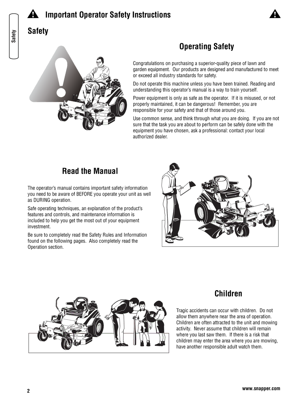
Children
Tragic accidents can occur with children. Do not allow them anywhere near the area of operation. Children are often attracted to the unit and mowing activity. Never assume that children will remain where you last saw them. If there is a risk that children may enter the area where you are mowing, have another responsible adult watch them.
2 | www.snapper.com |
|