Section 3 - MAINTENANCE
WARNING
DO NOT attempt any adjustments, maintenance, service or repairs with the engine running. STOP engine. STOP blade. Engage parking brake. Remove key. Remove spark plug wire from spark plug and secure away from plug. Engine and components are HOT. Avoid serious burns, allow all parts to cool before working on machine.
WARNING
Blades are extremely sharp and can cause severe injuries. Wear heavy gloves when working on or handling blades. DO NOT use blades that show signs of wear or damage.
3.2.3. Check Mower Blade
1.Stop engine, stop blades. Engage parking brake. Remove key.
2.Carefully stand machine on rear bumper. IMPORTANT: If the machine will be on its rear bumper for longer than two hours, remove the battery. Refer to Section “BATTERY REMOVAL”.
3.Check torque of blade mounting nut. Torque nut to 60 to 90 ft. lbs. See Figure 3.3.
TORQUE BLADE MOUNTING NUT TO
FIGURE 3.3
4.Inspect blades carefully for wear or damage. Refer to Section “BLADE WEAR LIMITS”. Replace worn or damaged blades.
3.2.4.BLADE DRIVE & ENGINE TO DECK BELTS A) Check Blade Drive Belt
The blade drive consists of two belts. The engine to deck belt will require inspection and periodic adjustment. The deck belt requires inspection only.
B) Engine To Deck Belt
1.Stop engine. Stop blades. Engage parking brake. Remove key.
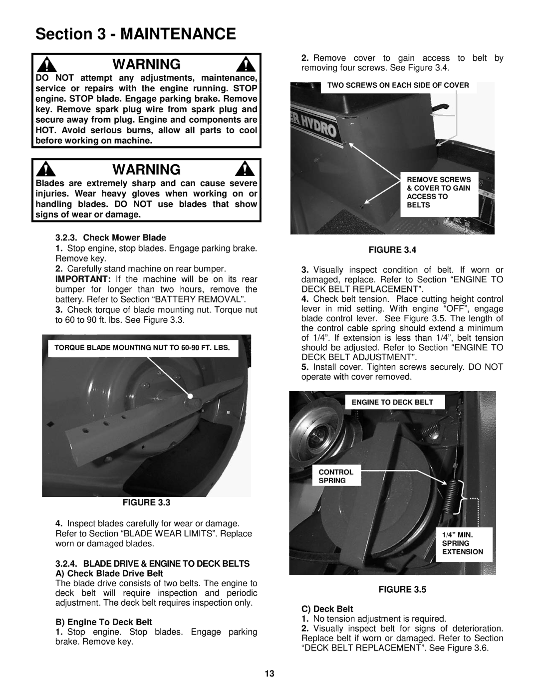
2.Remove cover to gain access to belt by removing four screws. See Figure 3.4.
TWO SCREWS ON EACH SIDE OF COVER
REMOVE SCREWS & COVER TO GAIN ACCESS TO BELTS
FIGURE 3.4
3.Visually inspect condition of belt. If worn or damaged, replace. Refer to Section “ENGINE TO DECK BELT REPLACEMENT”.
4.Check belt tension. Place cutting height control lever in mid setting. With engine “OFF”, engage blade control lever. See Figure 3.5. The length of the control cable spring should extend a minimum of 1/4”. If extension is less than 1/4”, belt tension should be adjusted. Refer to Section “ENGINE TO DECK BELT ADJUSTMENT”.
5.Install cover. Tighten screws securely. DO NOT operate with cover removed.
ENGINE TO DECK BELT
CONTROL
SPRING
1/4” MIN.
SPRING EXTENSION
FIGURE 3.5
C) Deck Belt
1.No tension adjustment is required.
2.Visually inspect belt for signs of deterioration. Replace belt if worn or damaged. Refer to Section “DECK BELT REPLACEMENT”. See Figure 3.6.
13