Section 1 - FAMILIARIZATION
BLADE
CONTROL
SEATLEVER ADJUSTMENT
KNOBS
FUEL TANK
NOTE: BLADE CONTROL LEVER ON LEFT
SIDE OF MACHINE, HIDDEN IN THIS VIEW
ENGINE
SPEED
CONTROL
IGNITION
SWITCH
CLUTCH BRAKE
PEDAL & PARK
BRAKE LATCH
|
| GROUND | |
CUTTING | |||
| SPEED | ||
DECK HANGER |
| ||
| PEDAL | ||
|
| ||
|
|
|
CUTTING
CUTTINGDECK
HEIGHT LEVER
DISCHARGE
DEFLECTOR
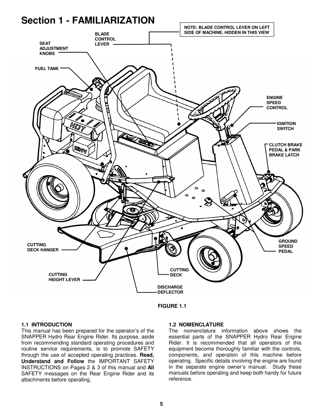
FIGURE 1.1
1.1 INTRODUCTION
This manual has been prepared for the operator’s of the SNAPPER Hydro Rear Engine Rider. Its purpose, aside from recommending standard operating procedures and routine service requirements, is to promote SAFETY through the use of accepted operating practices. Read, Understand and Follow the IMPORTANT SAFETY INSTRUCTIONS on Pages 2 & 3 of this manual and All SAFETY messages on the Rear Engine Rider and its attachments before operating.
1.2 NOMENCLATURE
The nomenclature information above shows the essential parts of the SNAPPER Hydro Rear Engine Rider. It is recommended that all operators of this equipment become thoroughly familiar with the controls, components, and operation of this machine before operating. Specific details involving the engine are found in the separate engine owner’s manual. Study these manuals before operating and keep both handy for future reference.
5